Multi Pro 5800Hydraulic System Page 5 − 76
Spray Pump Control Manifold Service
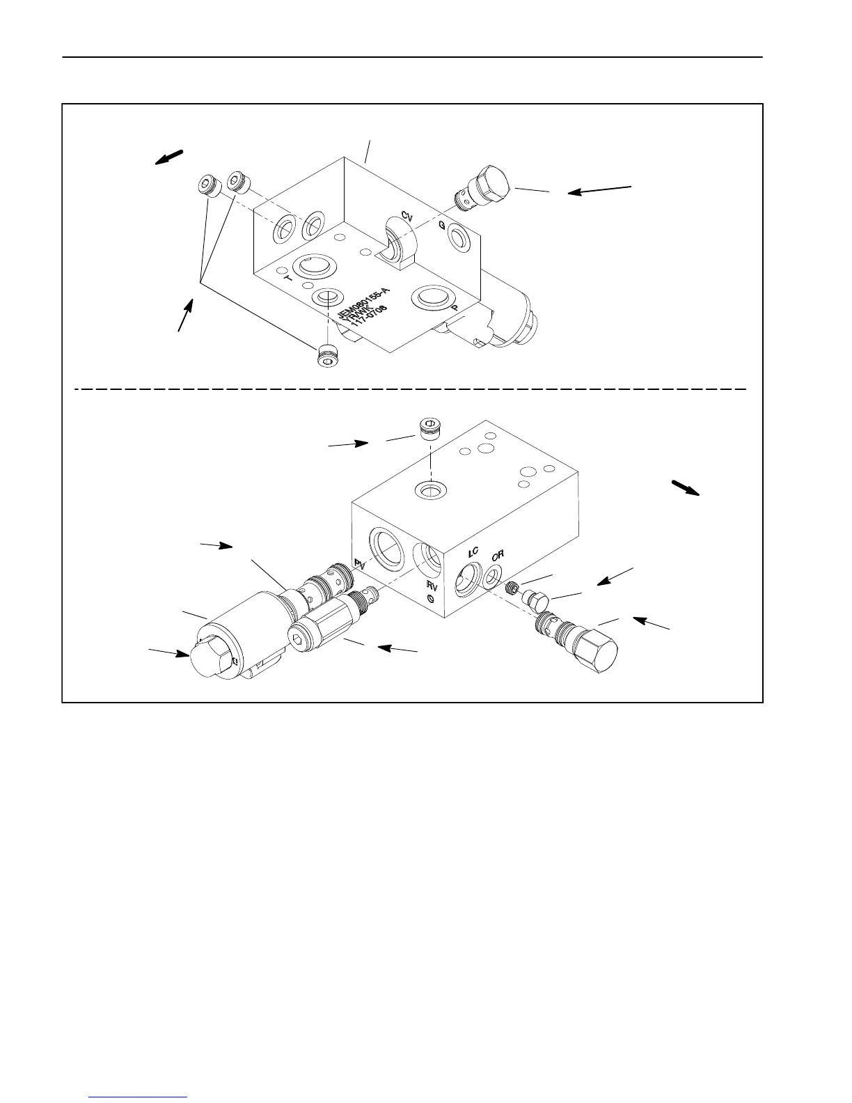
Figure 55
1. #6 zero leak plug with O−ring
2. Spray pump control manifold
3. Check valve (port CV)
4. Solenoid coil
5. Proportional control valve (port PV)
6. Relief valve (port RV)
7. Pressure compensator (port LC)
8. #4 zero leak plug with O−ring
9. Orifice (0.040)
2
3
6
8
9
5
7
4
1
1
FRONT
FRONT
20 ft−lb
(27 N−m)
25 ft−lb
(34 N−m)
35 ft−lb
(47 N−m)
10 ft−lb
(14 N−m)
25 ft−lb
(34 N−m)
25 ft−lb
(34 N−m)
25 ft−lb
(34 N−m)
20 ft−lb
(27 N−m)
The ports on the manifold are marked for easy identifica-
tion of components. Example: P is the gear pump con-
nection port and CV is the location for the check valve
(see Hydraulic Schematic in Chapter 8 − Foldout Draw-
ings to identify the function of the hydraulic lines and car-
tridge valves at each manifold port).
NOTE: The spray pump control manifold uses several
zero leak plugs. These plugs have a tapered sealing
surface on the plug head that is designed to resist vibra-
tion induced plug loosening. The zero leak plugs also
have an O−ring as a secondary seal. If zero leak plug re-
moval is necessary, lightly rap the plug head using a
punch and hammer before using an allen wrench to re-
move the plug: the impact will allow plug removal with
less chance of damage to the socket head of the plug.

 Loading...


