Multi Pro 5800Page 6 − 88Electrical System
Tank Clean Rinse Pump Switch (Optional)
The clean tank rinse kit switch is used to turn the optional
rinse pump ON or OFF. Pressing the upper portion of the
switch energizes the rinse pump for a 60 second timed
period. Pressing the lower portion of the switch ener-
gizes the rinse pump momentarily (pump remains ON
only as long as the switch is pressed). Kits with serial
numbers below 316000000 use an illuminated switch.
The light on the switch will illuminate when the rinse
pump is operating. The Toro Electronic Controller (TEC)
monitors the operation of the rinse kit switch as an input
and provides an output to energize the rinse pump relay.
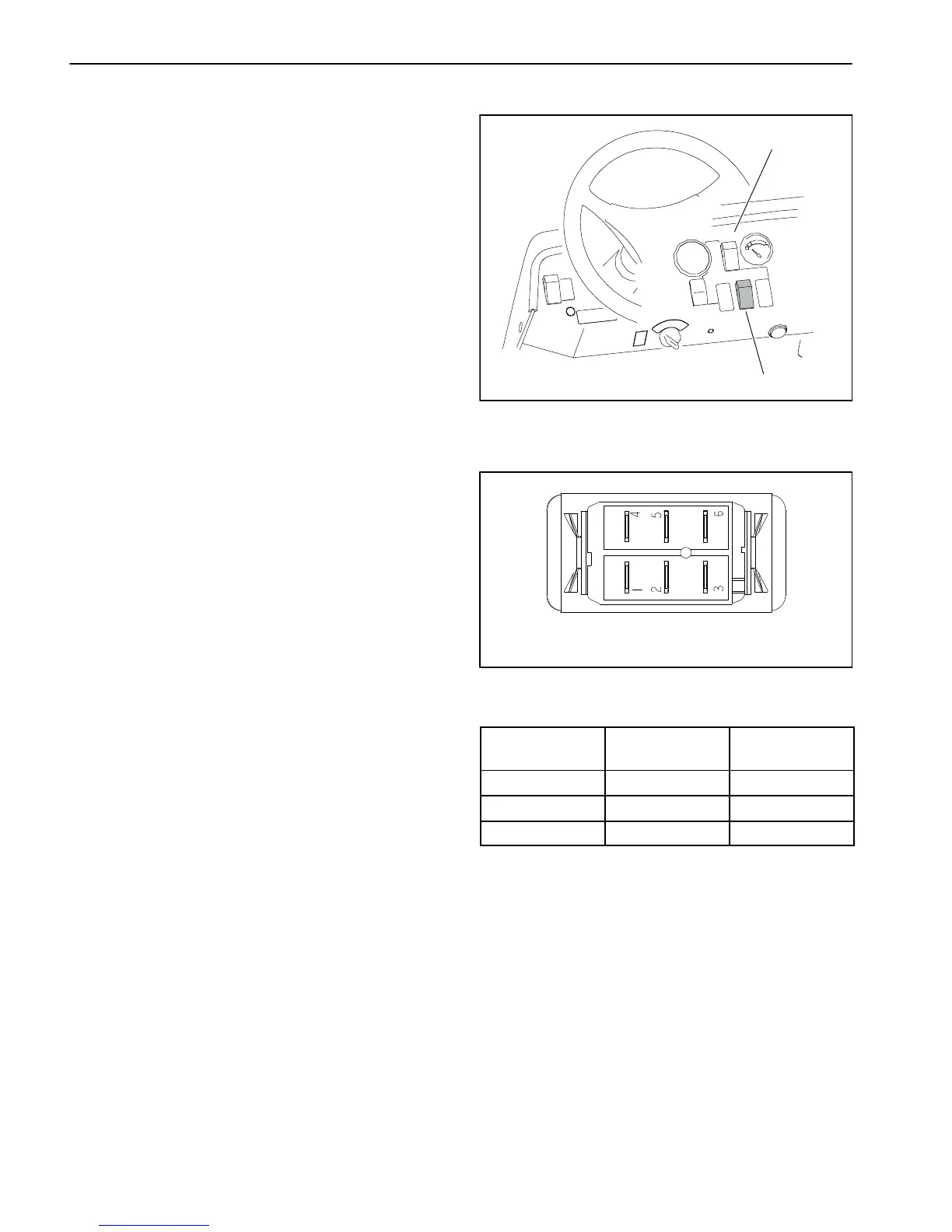
The rinse kit switch is located on the instrument panel to
the right of the steering column (Fig. 132).
Testing
The clean rinse kit switch and its circuit wiring can be
tested as a TEC input or qualifier using the InfoCenter
Display (see InfoCenter Display − Diagnostics Screen in
this chapter). If testing determines that the switch and
circuit wiring are not functioning correctly, proceed with
the following test procedure:
1. Park machine on a level surface, stop engine and en-
gage parking brake. Remove key from ignition switch.
2. Locate clean rinse kit switch under instrument panel
and unplug machine wire harness connector from
switch.
3. With the use of a multimeter (ohms setting), the clean
rinse kit switch functions may be tested to determine
whether continuity exists between the various terminals
for each switch position. The switch terminals are
marked as shown (Fig. 133) and the circuitry of the
switch is shown in the table (Fig. 134). Verify continuity
between switch terminals.
4. Replace switch if testing determines that it is faulty.
5. If the switch tests correctly and a circuit problem still
exists, check wire harness (see Electrical Schematic
and Wire Harness Drawings in Chapter 11 − Foldout
Drawings in this manual).
6. Connect the harness connector to the clean rinse kit
switch after testing.
1. Instrument panel 2. Rinse kit switch (opt.)
Figure 132
1
2
Figure 133
BACK OF SWITCH
SWITCH
POSITION
CLOSED
TERMINALS
OPEN
TERMINALS
ON 2 + 1, 5 + 4 2 + 3, 5 + 6
OFF NONE ALL
MOMENTARY 2 + 3, 5 + 6 2 + 1, 5 + 4
Figure 134
NOTE: Clean tank rinse kit switch terminals 4, 5 and 6
are not used on Multi Pro 5800 machines.

 Loading...


