Multi Pro 5800Page 6 - 46Electrical System
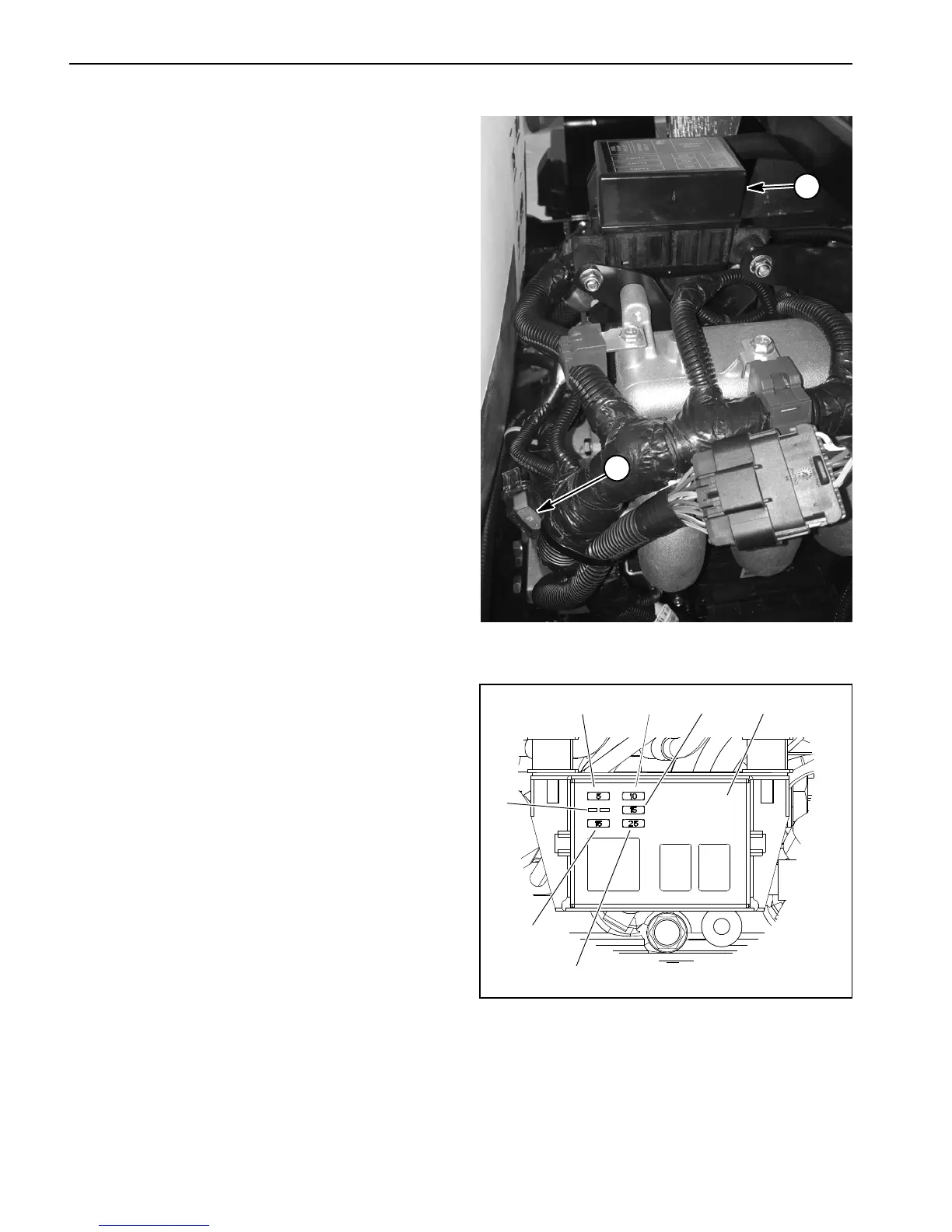
Engine Fuses (Gasoline Engines Only)
The engine fuses that protect the Kubota gasoline en-
gine electrical circuits are installed in the engine power
center located on top of the engine (Fig. 51).
In addition to the fuses in the power center, a 60 Amp
Maxi- fuse is included in the Kubota engine wire harness
to protect the charging circuit. This Maxi- fuse resides in
an in- line fuse holder near the engine starter motor
(Fig. 51).
Identification and Function
Use Figure 52 to identify each individual fuse and its cor-
rect amperage. Engine fuses have the following func-
tion:
Fuse F- 1 (5 Amp): Protects engine VSW (ignition
switch voltage) circuit power supply.
FuseF-2(10Amp):Protects engine ECU p ower sup-
ply.
Fuse F- 3: Not used.
FuseF-4(15Amp):Protects power supply for engine
electrical system.
FuseF-5(15Amp):Protects fuel pump circuit power
supply.
Fuse F- 6 (25 Amp): Protects starter motor circuit pow-
er supply.
Fuse Testing
1. Make sure that ignition switch is in the OFF position
and key is removed from ignition switch.
2. Remove engine shroud (attached to back of seat
base) to access engine fuses.
3. Remove fuse(s) from the engine power center o r
fuse holder for testing. Fuse should have continuity be-
tween fuse terminals.
IMPORTANT: If fuse replacement is necessary,
make sure that replacement fuse has the correct
amperage rating.
4. Replace f use if testing determines that it is faulty.
5. Install engine shroud.
Figure 51
1. Engine power center 2. 60 Amp Maxi- fuse
1
2
1. FuseF-1(5Amp)
2. Fuse F- 2 (10 Amp)
3. Fuse F- 3 (not used)
4. Fuse F- 4 (15 Amp)
5. Fuse F- 5 (15 Amp)
6. Fuse F- 6 (25 Amp)
7. Engine power center
Figure 52
21
3
4
5
6
7

 Loading...


