Multi Pro 5800 Page 6 − 53 Electrical System
Speed−Lock Switch
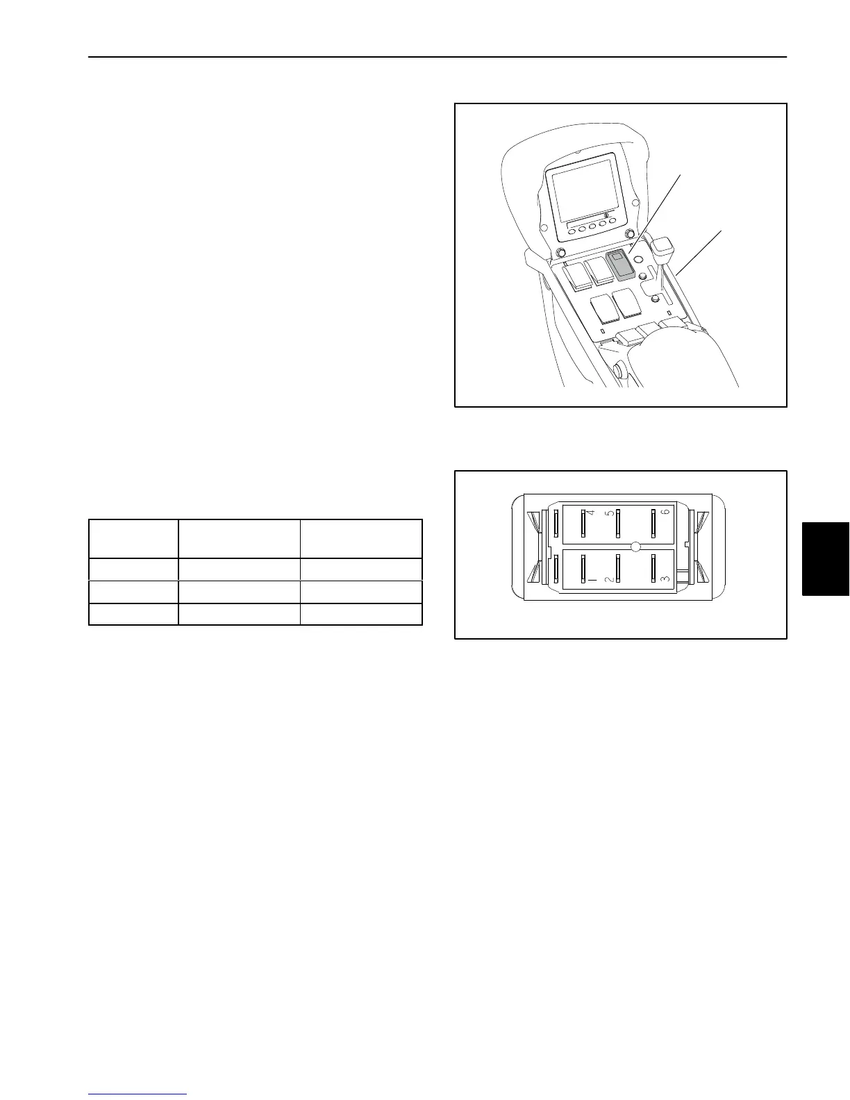
The speed−lock switch is located on the console assem-
bly (Fig. 68). This switch energizes the speed lock coil
to allow the operator to maintain a constant ground
speed. The switch includes a light that should illuminate
when the switch is in the ON position.
Testing
1. Park machine on a level surface, stop engine and en-
gage parking brake. Remove key from ignition switch.
2. Remove RH console cover to gain access to speed
lock switch (see Console Assembly in the Service and
Repairs section of Chapter 9 − Chassis in this manual).
3. Locate the switch to be tested and disconnect the
wire harness electrical connector from the switch.
4. With the use of a multimeter (ohms setting), the
switch functions may be tested to determine whether
continuity exists between the various terminals for each
position. The switch terminals are marked as shown
(Fig. 69) and the circuitry of the speed−lock switch is
shown in the chart (Fig. 67). Verify continuity between
switch terminals.
SWITCH
POSITION
CLOSED
TERMINALS
OPEN
TERMINALS
OFF 2 + 1, 5 + 4 ALL
ON 2 + 3 2 +1, 5 + 4, 5 + 6
SET 2 + 3, 5 + 6 2 +1, 5 + 4
Figure 67
5. Terminals 7 (−) and 8 (+) are used for the indicator
light in the switch. The light should be illuminated when
the speed−lock is energized (holding the traction pedal
stationary).
6. To test switch light, apply 12 VDC to terminal 8 (+)
and ground terminal 7 (−). The light should illuminate.
7. Replace switch if necessary.
8. If the switch tests correctly and a circuit problem still
exists, check the wire harnesses (see Electrical Sche-
matics and Wire Harness Drawings and Diagrams in
Chapter 11 − Foldout Drawings in this manual).
9. Connect the wire harness connector to the switch af-
ter testing is complete.
10.Secure RH console cover to machine (see Console
Assembly in the Service and Repairs section of Chapter
9 − Chassis).
1. Console assembly 2. Speed lock switch
Figure 68
1
2
Figure 69
BACK OF SWITCH
87
NOTE: Speed−lock switch terminals1 and 4 are not
used on Multi Pro 5800 machines.
Electrical
System

 Loading...


