Multi Pro 5800Page 6 − 56Electrical System
Spray Pump Enable and Agitation Switches
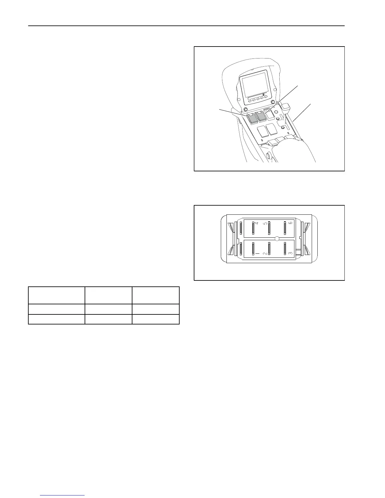
The spray pump enable (on/off) and agitation (on/off)
switches are located on the control console (Fig. 77).
Both switches are inputs to the TEC. The switch in-
cludes a light that should illuminate when the switch is
in the ON position.
Testing
The spray pump enable and agitation switches and their
circuit wiring can be tested as TEC inputs or qualifiers
using the InfoCenter Display (see InfoCenter Display −
Diagnostics Screen in this chapter). If testing deter-
mines that the switch and circuit wiring are not function-
ing correctly, proceed with the following test procedure:
1. Park machine on a level surface, stop engine and en-
gage parking brake. Remove key from ignition switch.
2. Remove console cover(s) to gain access to switch to
be tested (see Console Assembly in Chapter 9 − Chas-
sis in this manual).
3. Locate the switch and disconnect the wire harness
electrical connector from the switch.
4. With the use of a multimeter (ohms setting), the
switch functions may be tested to determine whether
continuity exists between the various terminals for each
position. The switch terminals are marked as shown
(Fig. 78) and the circuitry of the spray pump enable and
agitation switches is shown in the chart (Fig. 76). Verify
continuity between switch terminals.
SWITCH
POSITION
CLOSED
TERMINALS
OPEN
TERMINALS
OFF 2 + 1, 5 + 4 2 + 3, 5 + 6
ON 2 + 3, 5 + 6 2 + 1, 5 + 4
Figure 76
5. To test switch light, apply 12 VDC to terminal 8 (+)
and ground terminal 7 (−). The light should illuminate.
6. Replace switch if necessary.
7. If the switch tests correctly and a circuit problem still
exists, check the wire harnesses (see Electrical Sche-
matics and Wire Harness Drawings and Diagrams in
Chapter 11 − Foldout Drawings in this manual).
8. Connect the wire harness connector to the switch af-
ter testing.
9. Install console covers (see Console Assembly in
Chapter 9 − Chassis of this manual).
1. Console assembly
2. Pump switch
3. Agitation switch
Figure 77
1
2
3
Figure 78
BACK OF SWITCH
87
NOTE: Spray pump enable and agitation switch termi-
nals 1 and 4 are not used on Multi Pro 5800 machines.

 Loading...


