Multi Pro 5800Page 8 − 42GeoLink Spray System
Guidance and Rate Management System
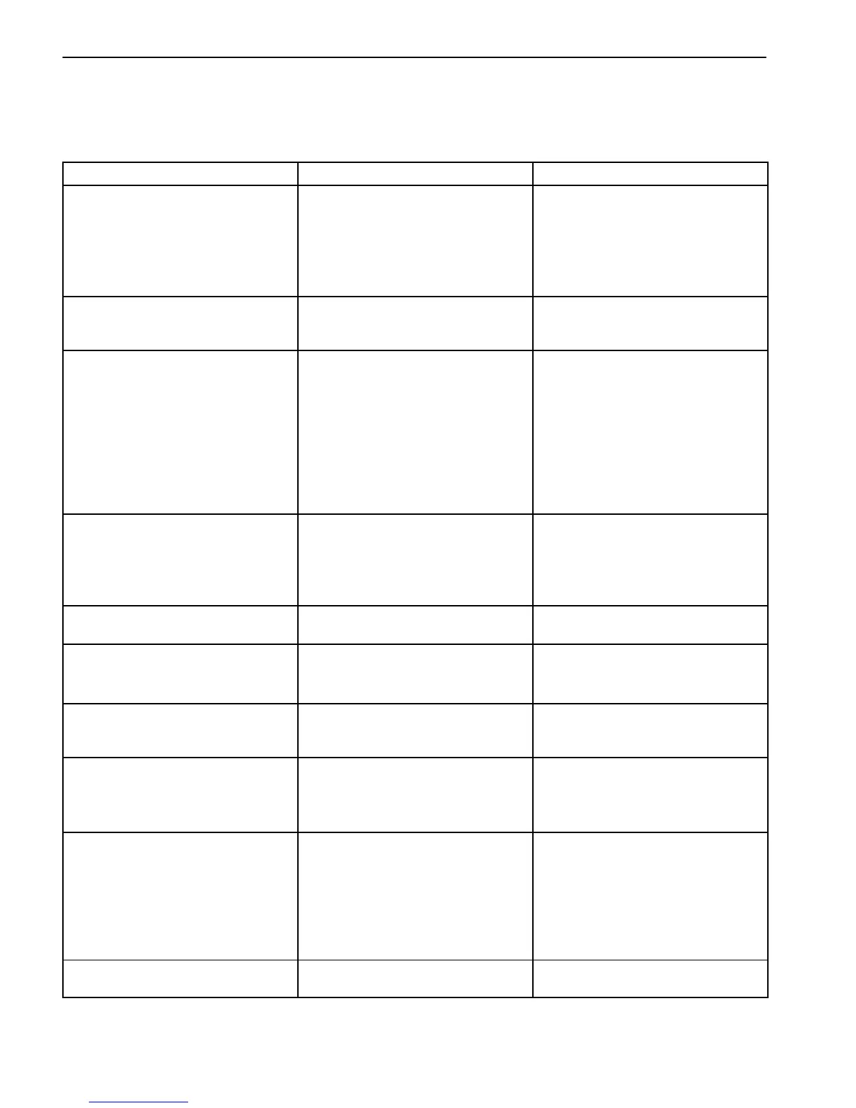
Use the following tables to assist in troubleshooting spe-
cific issues with the guidance and rate management
(dry) portion of the spray system.
Problem
Possible Cause Corrective Action
There is no power to the display. The connectors are not installed
correctly
The fuse(s) for the GeoLink sys-
tem blown
The battery connections are loose
Ensure the connectors are in-
stalled correctly at the back of the
display
Replace the fuse(s)
Secure the battery connections
The monitor is frozen There is a malfunction with the
software
Hold in the green button on the
back of the display until the front
LED lights flash
The sprayer does not spray The virtual or external master
switch is OFF
The boom section switches on the
operator console (between the
seats) are OFF
No job and boundary are created
The incorrect nozzle is selected in
sprayer−control setup menu
Set the virtual or external master
switch to ON
Set the boom section switches on
the operator console (between the
seats) to ON
Create a job and boundary
Select the correct nozzle in
sprayer−control setup menu that
matches the nozzles being used
The No GPS alarm is on The display is not connected to
GPS receiver correctly
The machine is under trees or oth-
er obstructions
Ensure the connections are in-
stalled correctly
Allow the machine to make con-
nection after driving under obstruc-
tions
The sprayer sprays outside bound-
aries
The auto section control (ASC) is
set to unlimited or OFF
Set the auto section control (ASC)
to field boundary
You cannot create boundaries The display is not in standard op-
erating mode
There is no field created
Switch the user profile to standard
operating mode
Create a field
The machine is not shown on the
screen
The display screen map has been
moved (panned)
Select the center−map under
sprayer icon on the view controls
menu
The lights are not blinking on the
GPS receiver located on the
ROPS
There is no power to the GPS re-
ceiver
The GPS receiver (AGI−4) is off−
line
Ensure the connectors are in-
stalled correctly
The pressure is not high enough The nozzle size used is incorrect
The nozzle size selected in the
display does not match the noz-
zles on the booms
The agitation is set too low
Refer to the nozzle selection chart
for the proper nozzle sizing
Ensure the nozzle size selected in
the display matches the boom noz-
zles
Adjust the agitation until the de-
sired pressure is realized
The LED lights on the controller
(ASC−10) are not on
There is no power to the controller
(ASC−10)
Ensure the connectors are in-
stalled correctly