Multi Pro 5800Hydraulic System Page 5 − 84
Steering Cylinder Service
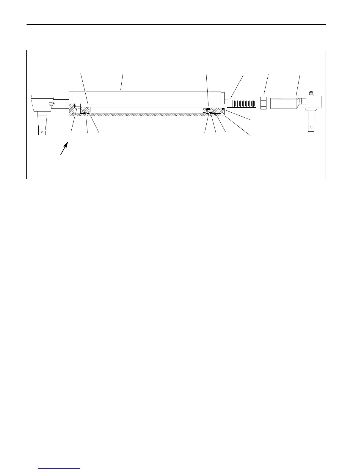
1. Retaining ring
2. O−ring
3. Head
4. Backup ring
5. O−ring
6. Shaft
7. Rod seal
8. Piston
9. Uni−ring
10. Lock nut
11. Barrel
12. Dust seal
13. Ball joint
14. Jam nut
Figure 62
5134
12
13
8910
711 62 14
40 ft−lb
(54 N−m)
Disassembly (Fig. 62)
1. Remove oil from the steering cylinder into a drain pan
by slowly pumping the cylinder shaft. Plug both ports
and clean the outside of the cylinder.
IMPORTANT: Prevent damage when clamping the
hydraulic cylinder into a vise. Do not close vise
enough to distort the barrel.
2. Mount end of steering cylinder in a vise. Remove re-
taining ring that secures head into barrel.
3. Remove plugs from ports. Extract shaft, head and
piston by carefully twisting and pulling on the shaft.
IMPORTANT: Do not clamp vise jaws against the
shaft surface. Protect shaft surface before mount-
ing in a vise.
4. Mount shaft securely in a vise by clamping on the end
of the shaft. Remove lock nut and piston from the shaft.
Slide head off the shaft.
5. Remove Uni−ring and O−ring from the piston.
6. Remove O−ring, back−up ring, rod seal and dust
seal from the head.
Assembly (Fig. 62)
1. Make sure all parts are clean before reassembly.
2. Coat new O−rings, Uni−ring, rod seal and back−up
ring with clean hydraulic oil.
A. Install Uni−ring and O−ring to the piston.
B. Install O−ring, back−up ring, rod seal and dust
seal to the head.
IMPORTANT: Do not clamp vise jaws against the
shaft surface. Protect shaft surface before mount-
ing in a vise.
3. Mount shaft securely in a vise by clamping on the end
of the shaft.
A. Coat shaft with a light coating of clean hydraulic
oil.
B. Slide head assembly onto the shaft. Install piston
and lock nut onto the shaft. Torque lock nut 40 ft−lb
(54 N−m) to secure assembly.
C. Remove shaft from the vise.

 Loading...


