Multi Pro 5800 ChassisPage 9 − 21
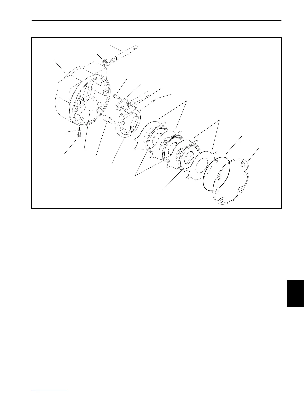
Brake Inspection and Repair
1. Brake housing (LH shown)
2. Seal
3. Pull rod
4. Clevis pin
5. Link
6. Hitch pin (2)
7. Stationary disc
8. Rotating disc
9. Retaining ring
10. Gasket
11. Rotating actuator
12. Extension spring (3)
13. Ball (3)
14. Plug (2)
15. O−ring
Figure 22
3
2
4
5
6
7
8
9
10
14
13
12
11
15
1
8
7
5
Brake Inspection and Repair (Fig. 22)
1. Scrape gasket material (item 10) from brake housing
and planetary wheel drive mounting surfaces.
2. Remove retaining ring (item 9).
3. Remove four (4) stationary discs (item 7) and three
(3) rotating discs (item 8).
4. Remove three (3) extension springs (item 12).
5. Remove actuator assembly (items 3, 4, 5, 6 and 11)
and three (3) balls (item 13).
6. Remove seal (item 2) from brake housing.
7. Wash parts in cleaning solvent. Inspect components
for wear or damage.
8. Reverse steps 2 through 6 to assemble brakes,
installing new parts as necessary. Install a new seal
(item 2).
9. Use a new gasket (item 10) when installing the brake
assembly to machine.
Chassis

 Loading...


