Multi Pro 5800Page 6 − 38Electrical System
Engine Faults (Gasoline Engines Only)
Engine faults are generated by the by the Kubota engine
Electronic Control Unit (ECU) to identify an electrical
system malfunction (fault) pertaining to the engine dur-
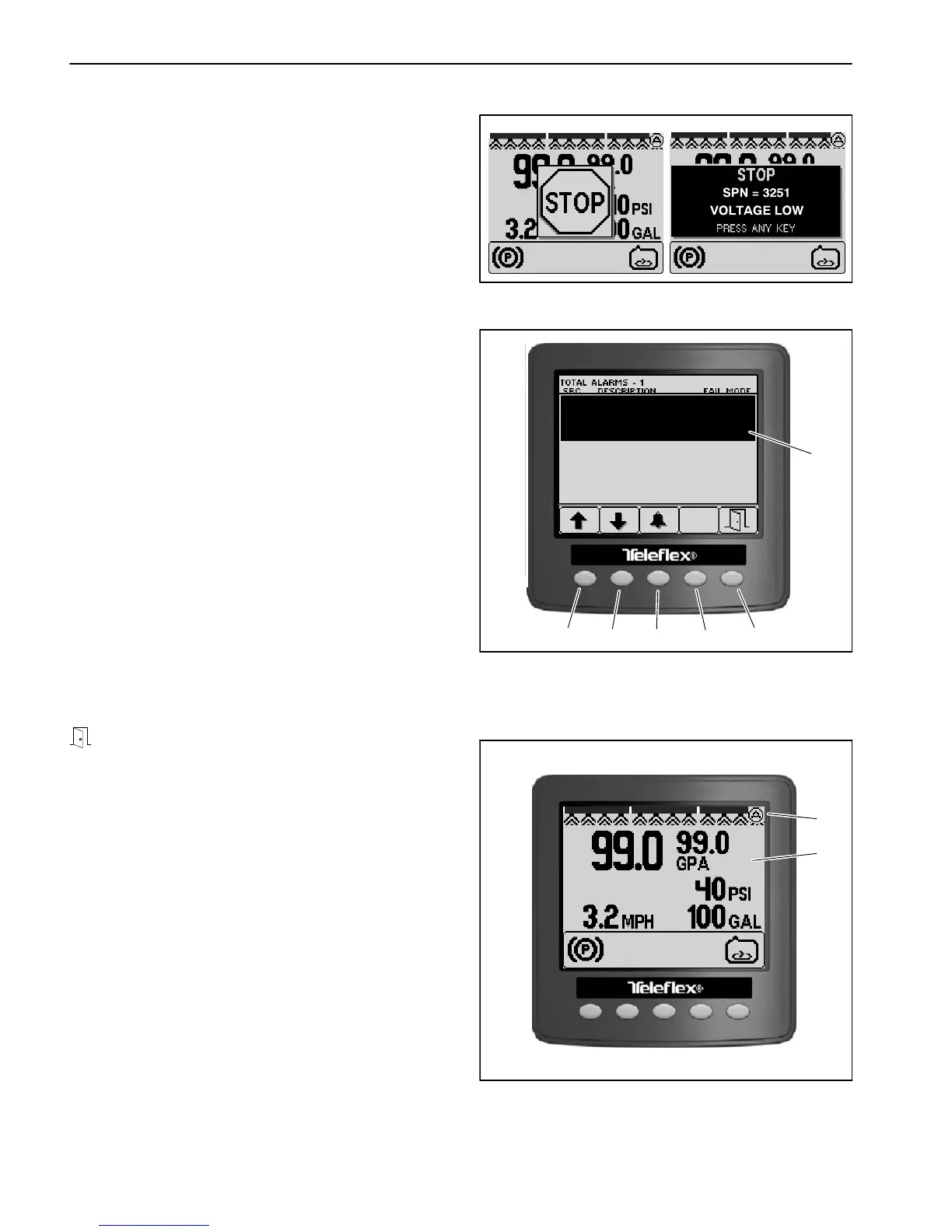
ing operation. When an engine fault occurs, an audible
alarm will sound and the InfoCenter will display informa-
tion about the fault. Depending on the severity of the
fault, a STOP icon may display as well (Fig. 42).
The Toro Electronic Controller (TEC) can also generate
electrical faults. The faults generated by the TEC are
specific to the machine (see Machine Faults in this chap-
ter for additional information).
If an engine fault occurs:
1. Press any key to remove the fault information panel
from Operator Information Screen. The audible alarm
will continue to sound.
2. The fault description will be displayed on the Info-
Center (Fig. 43). Press button 3 to silence the audible
alarm. Press buttons 1 and 2 to scroll through the list of
active engine faults.
3. If a STOP fault is displayed on the InfoCenter, the op-
erator should cease operation of the machine and the
engine as quickly and as safely as possible to reduce
damage to the engine.
4. If a CHECK ENGINE fault is displayed on the Info-
Center, the operator should take the machine for service
as soon as possible.
5. Return to the previous screen by pressing button 5
An icon will appear in the upper left corner of the Opera-
tors Information screen as long as an engine fault is ac-
tive (Fig. 44). In order to clear the displayed fault, the
engine problem has to be resolved. See the Kubota Di-
agnosis and Workshop Manual for additional informa-
tion.
NOTE: Engine faults that are no longer active should
be stored in the Kubota Engine Electronic Control unit
(ECU) and should be viewed by using the Kubota Gasol-
ine Service Tool (KGST) and software. Contact your Au-
thorized Toro Distributor for assistance.
Figure 42
1. IDLE
0X00 ENG HRS − 100 VOLTAGE LOW
SPN − 3251 FMI − 4
OCC CNT − 1
Figure 43
1. Button 1
2. Button 2
3. Button 3
4. Button 4
5. Button 5
6. Engine fault description
1
2
3
4
5
6
1. Operator information
screen
2. Active engine fault icon
Figure 44
2
1

 Loading...


