Multi Pro 5800Page 8 − 56GeoLink Spray System
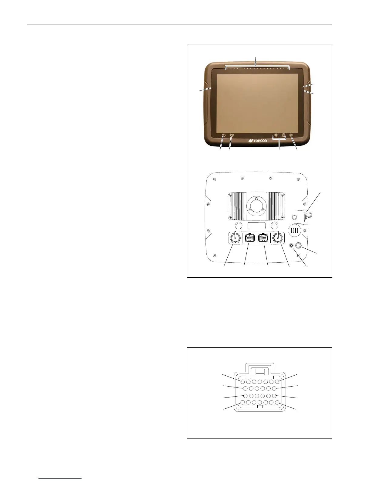
X25 or X30 Control Console
The X25 or X30 control console is mounted to the ma-
chine instrument panel. The console includes a battery
to safely shut the console down if power to the console
is suddenly lost. In addition to the controls that appear
on the various sub−menus and screens, the console in-
cludes the following LED indicator lights along the top
and sides of the console, and control buttons at the bot-
tom of the console:
LED light bar − displays the direction and distance the
sprayer is currently traveling in relation to a wayline.
The LEDs will change from blue to green to orange
and red as the sprayer moves further from the way-
line.
Light sensor − used to set the display brightness
based on ambient light
Console battery status LED
Green = fully charged +7.5 VDC
Yellow = partially charged −7.2 VDC
Red = discharged
Combined with Blue flashing = charging
Supply status LED
Green—good supply +12 VDC
Yellow—low supply −12 VDC
Red—very low supply or off −9VDC
Toolbar (displayed on X25 consoles by swiping up-
wards from the base of the screen)
Help button − pressing the help button allows the
operator to view icon names on the screen without
opening the icon menu or initiating the icon com-
mand
USB eject button − use whenever you remove a
USB device from the console (the primary USB port
is located on the left side of the console)
Screen brightness control buttons
Day/Night mode button − one touch control of
screen brightness and contrast settings for better
viewing in light or dark conditions
Unswitched power is provided to the console as long as
the battery cables are connected to the battery. A 10
amp fuse provides circuit protection for the unswitched
power to the console. A switched power circuit is also re-
quired to operate the console.
A twenty−six (26) pin connector is used at the control
console. The layout of the wire harness connector is
shown (Fig. 66). See the electrical schematics and wire
harness drawings and diagrams in Chapter 11 − Foldout
Drawings in this manual for additional information.
1. LED light bar
2. Battery status
3. Supply status
4. Light sensor
5. Help button
6. USB eject button
7. Screen brightness
control buttons
8. Day/Night mode button
9. USB port
10. Power button
11. CAT5 cable connector
12. Harness connecter
13. Harness connecter
(not used)
14. USB port (auxiliary)
15. Reset button
Figure 65
X30 CONSOLE (back)
9
10
11 12 13 14 15
X30 CONSOLE (front)
56 7
2
8
3
4
1
Figure 66
WIRE HARNESS CONNECTOR FOR X25 AND X30
1
7
13
19
26
8
14
26
12 VDC UNSWITCHED − PIN 1
12 VDC SWITCHED − PIN 2
GROUND − PIN 3

 Loading...


