Multi Pro 5800 Page 6 − 3 Electrical System
Kubota Gasoline Engine Electronic Control Unit (ECU)
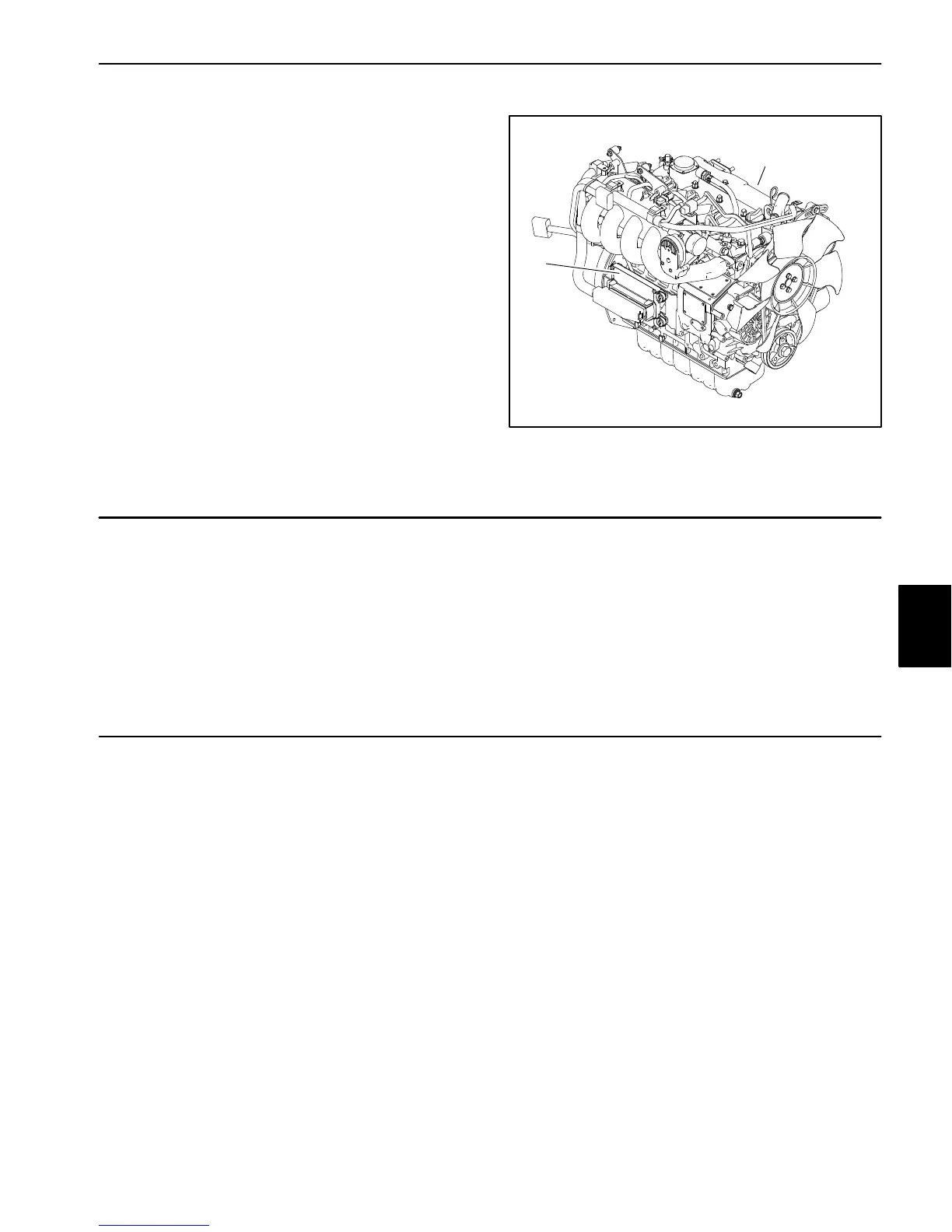
The Kubota gasoline engine that powers Multi Pro 5800
models 41394 and 41594 uses an Electronic Control
Unit (ECU) for engine management. The engine ECU
communicates with the Toro Electronic Controller (TEC)
and the InfoCenter display on the machine. The gaso-
line engine ECU is located on the right side of the en-
gine. All wire harness electrical connectors should be
plugged into the ECU before the machine ignition switch
is moved from the OFF position to either the ON or
START position.
If the engine ECU is to be disconnected for any reason,
make sure that the ignition switch is in the OFF position
with the key removed for a minimum of thirty (30) sec-
onds before disconnecting the engine ECU. Also, to pre-
vent possible ECU damage when welding on the
machine, disconnect the engine ECU from the machine
before welding.
Figure 2
1. Gasoline engine
2. Engine ECM
1
2
Kubota Engine Electrical Components
When servicing or troubleshooting the engine electrical
components, use the correct engine service manual and
troubleshooting manual. Also, for Gasoline engine pow-
ered units, your Toro Distributor can use the Kubota
Gasoline Service Tool (KGST) and software to confirm
the real−time engine running status and to offer timely
technical services. Contact your Toro distributor for as-
sistance in Kubota gasoline engine troubleshooting.
CAN−bus Communications
The TEC controller, the InfoCenter Display, and in the
case of gasoline engine powered machines the Kubota
Engine Controller communicate with each other on a
Controller Area Network (CAN) bus system. Using this
network allows the traction unit to fully integrate all the
different electrical components of the tractor and bring
them together as one. The CAN bus system reduces the
number of electrical components and connections used
on the machine and allows the number of wires in the
wire harness to be significantly reduced. The integration
of electrical functions also allows the InfoCenter Display
to assist with electrical system diagnostics.
Each of the components that is controlled by the CAN
bus link only needs four (4) wires to operate and commu-
nicate to the system: CAN High, CAN Low, power and
ground. The ignition switch needs to be in the RUN or
START position for the components on the network to be
active.
Two (2) specially designed, twisted wires form the CAN
bus. These wires provide the data pathways between
the components on the network. The engineering term
for these cables are CAN High and CAN Low. The bus
wires for the 12 VDC circuits are black/white and red/
white. At the end of the twisted pair of bus cables is a 120
ohm termination resistor.
IMPORTANT: The termination resistor at the end of
the bus wires is required for proper electrical sys-
tem operation.
Electrical
System

 Loading...


