Multi Pro 5800 Page 6 − 61 Electrical System
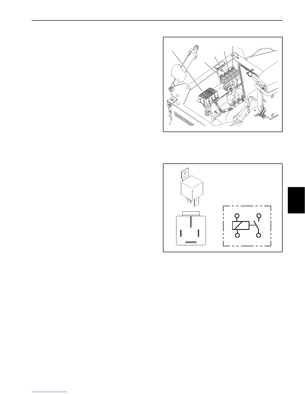
Relays with Four (4) Terminals
The Multi Pro 5800 uses a number of electrical relays
that have four (4) terminals. The relays is located under
the operator seat next to the fuse blocks (Fig. 87). The
relays can be identified by a tag near the relay wire har-
ness connector.
All Multi Pro 5800 machines use a four (4) terminal
main power relay to provide current to most of the
fuse protected circuits (TEC, InfoCenter display,
spray system components, speed lock, power point,
headlights and optional electric equipment). The
power relay is energized when the ignition switch is
in the RUN or START position.
Machines with diesel engines use a four (4) terminal
glow relay to provide current to the engine glow
plugs. The glow relay is energized by the Kubota
glow plug controller for approximately six (6) sec-
onds when the ignition switch is placed in the RUN/
PREHEAT position and while the ignition switch is
held in the START position.
If the machine is equipped with an optional clean
tank rinse kit, an additional four (4) terminal relay is
added to the electrical system. The rinse pump relay
is energized by the TEC when the rinse pump switch
is pressed.
If the machine is equipped with an optional hose reel
kit, an additional four (4) terminal relay is added to
the electrical system. The hose reel relay is ener-
gized when the hose reel motor switch is pressed.
The hose reel relay is located in the hose reel control
box (not shown).
Testing
1. Park machine on a level surface, stop stop engine
and engage parking brake. Remove key from ignition
switch.
2. Raise operator seat and locate the desired relay. Dis-
connect wire harness connector from the relay and re-
move the relay from the machine.
3. The relay terminals are marked as shown (Fig. 88).
NOTE: Prior to taking small resistance readings with a
digital multimeter, short the meter test leads together.
The meter will display a small resistance value (usually
0.5 ohms or less). This resistance is due to the internal
resistance of the meter and test leads. Subtract this val-
ue from from the measured value of the component you
are testing.
4. Using a multimeter, verify that coil resistance be-
tween terminals 86 and 85 is approximately 72 ohms.
1. Fuse blocks
2. Main power relay
3. Glow relay
(diesel engines only)
4. Optional kit relays
Figure 87
1
3
2
4
4
Figure 88
86 87
85 30
85 86
87
30
5. Connect multimeter (ohms setting) leads to relay ter-
minals 30 and 87. Ground terminal 86 and apply +12
VDC to terminal 85. The relay should make and break
continuity between terminals 30 and 87 as +12 VDC is
applied and removed from terminal 85.
6. Replace relay if testing determines that the relay is
faulty.
7. If the relay tests correctly and a circuit problem still
exists, check wire harness (see Electrical Schematic
and Wire Harness Drawings in Chapter 11 − Foldout
Drawings in this manual).
8. Install relay and connect to wire harness.
9. Lower and secure operator seat.
Electrical
System

 Loading...


