Multi Pro 5800 Page 8 − 77 GeoLink Spray System
Agitation Bypass Valve Service
The Multi Pro 5800 GeoLink spray system includes an
agitation bypass valve. The bypass valve is fully ser-
viceable. Use the following procedure for servicing the
agitation bypass valve.
IMPORTANT: Make sure to remove and neutralize
chemicals from spray components before removing
the pressure relief valve. Wear protective clothing,
chemical resistant gloves and eye protection during
repair.
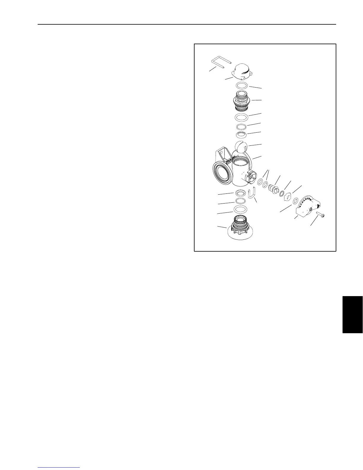
Disassembly (Fig. 81)
1. Locate the valve being serviced and remove the
screw, knob and O−ring from the valve.
2. Remove hoses, fittings, clamps and caps as neces-
sary to access valve end caps.
3. Rotate the end caps counterclockwise (unscrew)
and remove the end caps.
4. Rotate the valve stem until the slot in the stem and
valve ball are in−line with the valve body and remove the
valve ball.
5. Remove the valve stem fork, seat, and remove the
valve stem assembly.
6. Inspect the valve seats (item 4). Replace compo-
nents as necessary.
Assembly (Fig. 81)
NOTE: Replace, do not reuse gaskets and O−rings.
Coat O−rings and gaskets with vegetable oil or silicone
grease before installation to reduce damage during as-
sembly.
1. Install new O−rings on stem assembly. Install stem
assembly, seat and fork.
2. Rotate the valve stem until the slot in the stem is in−
line with the valve body and install the valve ball.
3. Apply silicone grease to seals and O−rings on end
caps and install end caps. Tighten end caps until seated.
Do not over−tighten end caps.
4. Install hoses, fittings, clamps and adapters previous-
ly removed.
5. Install either the actuator and actuator fork or knob
and screw.
1. Valve body
2. End cap
(flanged − clamp)
3. End cap
(male − fork)
4. Seat (2)
5. O−Ring (2)
6. O−Ring (2)
7. O−Ring
8. Ball (regulating)
9. Stem fork
10. O−Ring (2)
11. Stem
12. Washer
13. Stem seat
14. O−ring
15. Knob
16. Screw
17. Cap
18. Fork
Figure 81
11
12
13
14
15
16
17
18
1
2
3
4
4
5
5
6
6
7
8
9
10
GeoLink
Spray System

 Loading...


