Multi Pro 5800Page 8 − 70GeoLink Spray System
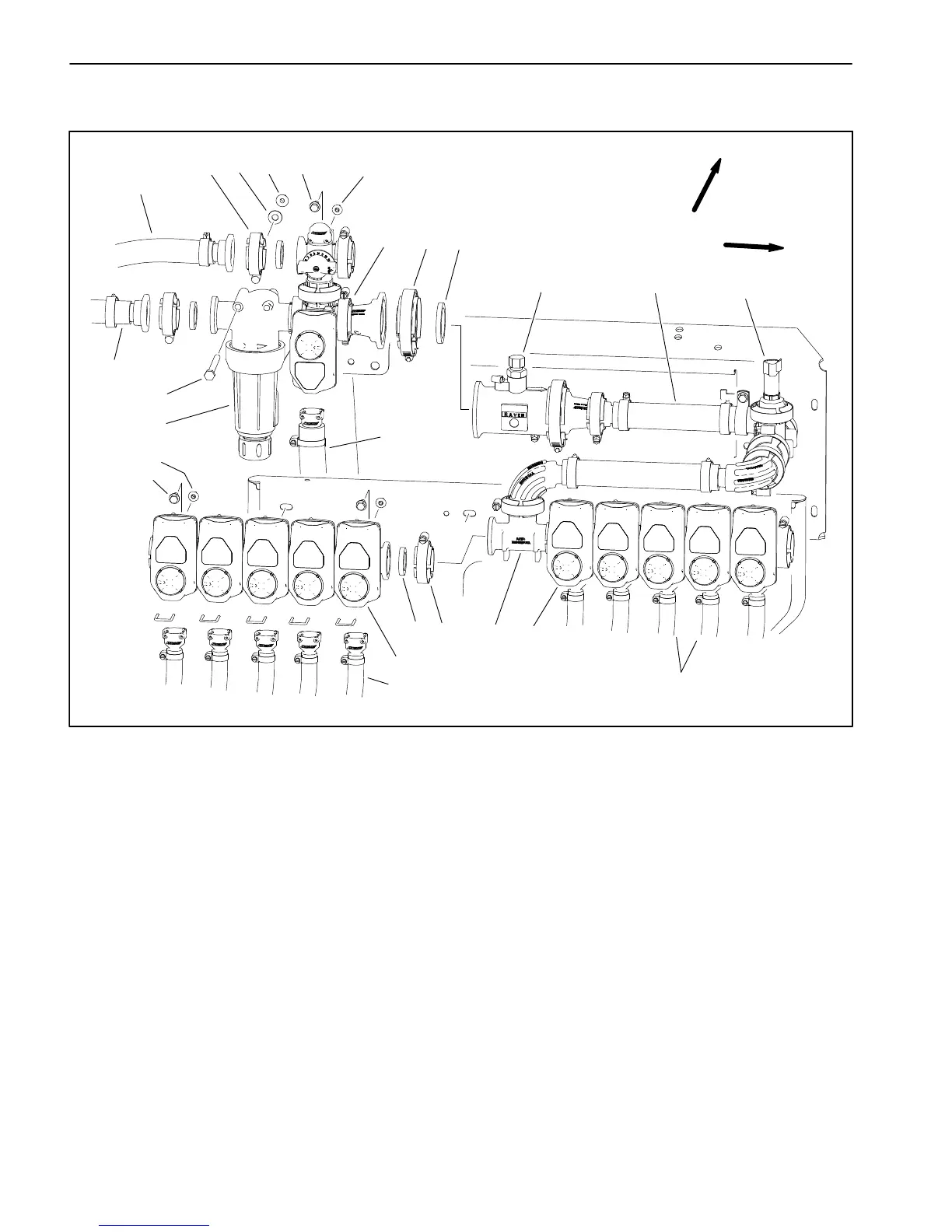
Spray Control Manifold Assembly
1. Agitation valve assy.
2. Flow meter
3. Elbow assembly
4. Pressure transducer
5. Nozzle valve assembly
(nozzles 1−6)
6. Tee
7. Nozzle valve assembly
(nozzles 7−12)
8. Gasket (4)
9. Clamp (4)
10. Gasket
11. Clamp
12. Cap screw (12)
13. Flange nut (12)
14. Cap screw (2)
15. Washer/spacer (2)
16. Flange nut (2)
17. High pressure filter bowl
18. Hose (agitation bypass)
19. Hose (supply from spray pump)
20. Hose (agitation supply)
21. Hose (nozzle supply − 10)
Figure 77
FRONT
RIGHT
11
12
12
13
13
14
15 16
17
18
19
20
21
1
2
3
4
5
6
7
8
9
9
10
21
The spray control manifold assembly includes the high
pressure spray product filter, the agitation valve assem-
bly, the flow meter, the pressure transducer and the noz-
zle valve assembly. Pressure transducer testing
information can be found in Chapter 6 − Electrical Sys-
tem in this manual.
NOTE: The spray control manifold may be configured
slightly different if the machine has any optional spray
system kits installed (e.g. foam marker, hose reel, educ-
tor, etc).

 Loading...


