Multi Pro 5800 Page 6 − 37 Electrical System
Machine Faults
Machine faults are generated by the Toro Electronic
Controller (TEC) to identify an electrical system mal-
function (fault) that occurs during machine operation.
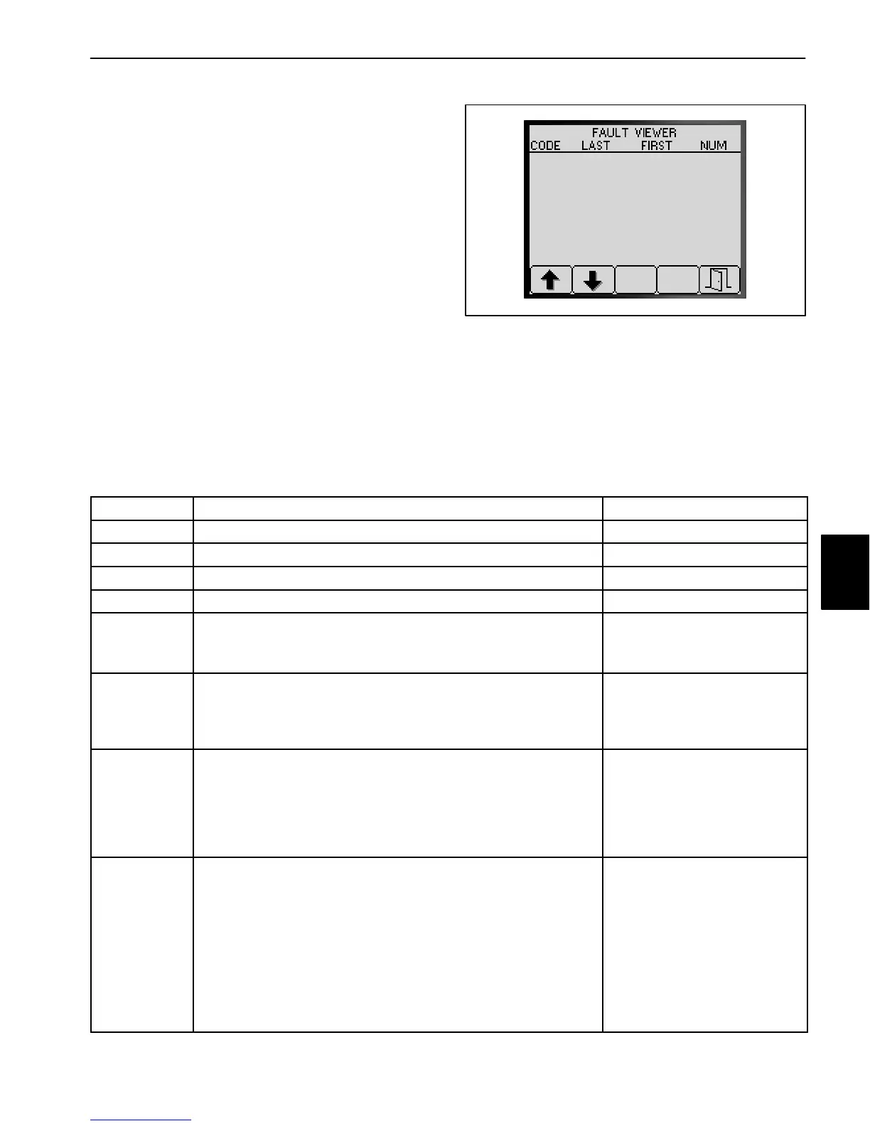
When a machine fault occurs, an audible alarm will
sound and the InfoCenter will display information about
the fault. Machine faults can be viewed via the InfoCen-
ter Diagnostic Screen Fault Viewer (Fig. 41). See Info-
Center Diagnostic Screen Fault Viewer in this chapter
for additional information.
For machines with gasoline engines, the Kubota Elec-
tronic Control Unit (ECU) can also generate electrical
faults. The faults generated by the ECU are specific to
the engine (see Engine Faults in this chapter for addi-
tional information).
The list below identifies the fault codes that are gener-
ated by the Toro Electronic Controller (TEC) to identify
an electrical system malfunction (fault) that occurred
during machine operation for revision D software. Use
the InfoCenter Display Diagnostics > Fault Viewer for
fault retrieval.
Figure 41
14 39.4 39.4 1
Fault Code Fault Description Recommended Action
1 TEC is faulty Replace TEC
2 One or more of the TEC output fuses (7.5 Amp) is faulty Replace fuse
3 Main power relay or circuit wiring is faulty Test main power relay
4 Charging system or circuit wiring is faulty Test charging system
14 InfoCenter software is not recognized by TEC Reload system software
Contact your Authorized Toro
Distributor
17 Starter timeout
(starter has been engaged for more than 30 seconds)
Allow starter to cool before
reattempting to start engine
Troubleshoot engine starting
issues
18 Neutral switch stuck in neutral position
(neutral switch reports it is in the neutral position, yet vehicle
speed is at or above 2 MPH for approximately 10 seconds)
Faults resets if speed drops below threshold, operator gets out
of seat, neutral switch indicates not in neutral, or system is
placed in Stationary Test Mode
Check Neutral Switch for ad-
justment and function
Check harness connections to
Neutral Switch
19 Spray System Fault − flow meter not working correctly or
harness fault (No flow detected when based upon boom, pump
and pressure it indicates there should be)
Spray pump is ON,Master Boom switch is ON, at least one
boom is ON, spray pressure is above 20 PSI, the booms have
been on long enough for the system to stabilize and vehicle
speed is fast enough for automatic application−rate control to
be enabled
Check the flow meter harness
for proper connection.
Confirm fluid flow at spray
nozzles. If so, flow should be
displayed on the flow rate me-
ter. If no fluid flow at spray
nozzles, begin checking the
spray system for a blockage.
Check flow meter for proper
function.
Electrical
System

 Loading...


