Multi Pro 5800Page 6 − 62Electrical System
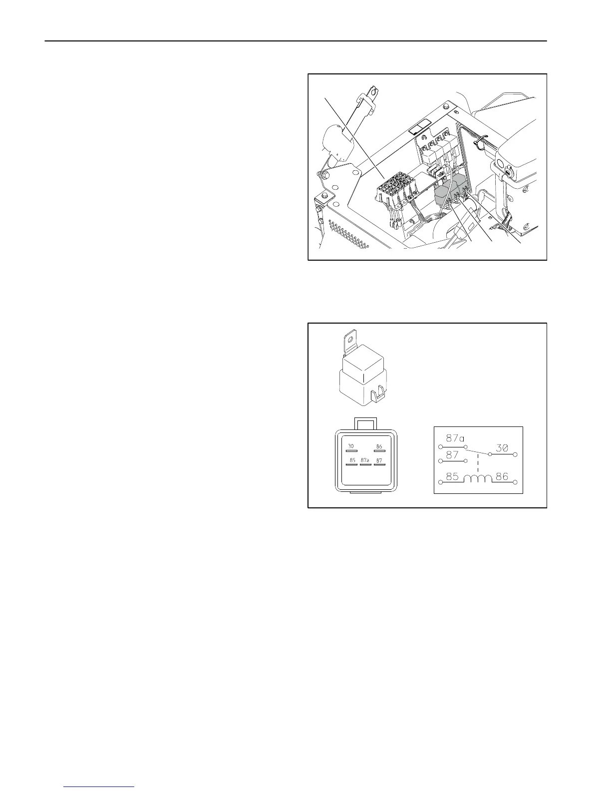
Relays with Five (5) Terminals
The Multi Pro 5800 uses a number of electrical relays
that have five (5) terminals. The relays is located under
the operator seat next to the fuse blocks (Fig. 89). The
relays can be identified by a tag near the relay wire har-
ness connector.
All Multi Pro 5800 machines use a five (5) terminal
speed lock relay to provide current to the speed lock
coil. The speed lock coil is energized when the speed
lock switch is moved to the SET position. The relay
remains energized until the brake pedal is de-
pressed or the speed lock switch is set to the OFF po-
sition.
Machines with diesel engines use a five (5) terminal
start relay to provide current to the engine starter mo-
tor solenoid. The start relay is energized by the Toro
Electronic Controller (TEC).
If the machine is equipped with an optional foam
marker kit, an additional four (5) terminal relay is
added to the electrical system. The foam marker
relay is energized when the foam marker power and
control switches are set to the ON position.
Testing
1. Park machine on a level surface, stop engine and en-
gage parking brake. Remove key from ignition switch.
2. Raise operator seat and locate the relay to be tested.
Disconnect wire harness connector from relay and re-
move relay from panel.
3. The relay terminals are marked as shown (Fig. 90).
NOTE: Prior to taking small resistance readings with a
digital multimeter, short the meter test leads together.
The meter will display a small resistance value (usually
0.5 ohms or less). This resistance is due to the internal
resistance of the meter and test leads. Subtract this val-
ue from from the measured value of the component you
are testing.
4. Using a multimeter, verify that coil resistance be-
tween terminals 85 and 86 is from 71 to 88 ohms.
5. Test normally open terminal by connecting multime-
ter (ohms setting) leads to relay terminals 30 and 87.
Ground terminal 86 and apply +12 VDC to terminal 85.
The relay should make and break continuity between
terminals 30 and 87 as +12 VDC is applied and removed
from terminal 85.
1. Fuse blocks
2. Speed lock relay
3. Start relay
(diesel engines only)
4. Optional kit relay
Figure 89
1
2
3
4
Figure 90
6. Test normally closed terminal by connecting multi-
meter (ohms setting) leads to relay terminals 30 and
87A. Apply +12 VDC to terminal 85. The relay should
make and break continuity between terminals 30 and
87A as +12 VDC is applied and removed from terminal
85.
7. Replace relay if testing determines that the relay is
faulty.
8. If the relay tests correctly and a circuit problem still
exists, check wire harness (see Electrical Schematic
and Wire Harness Drawings in Chapter 11 − Foldout
Drawings in this manual).
9. Install relay and connect to wire harness.
10.Lower and secure operator seat.

 Loading...


