Multi Pro 5800 Page 6 − 73 Electrical System
Fuel Level Sender (Gasoline Engines Only)
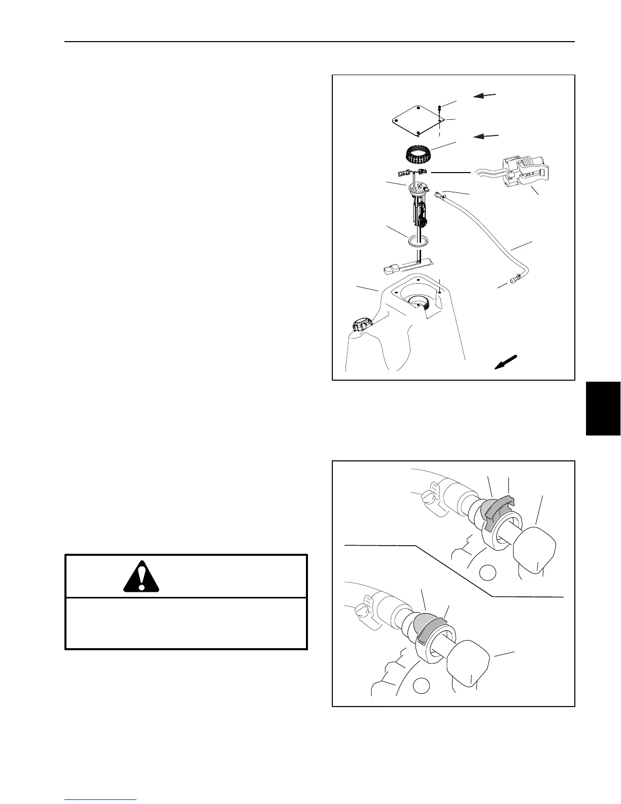
On Multi Pro 5800 machines with a Kubota gasoline en-
gine, the fuel sender is a component of the fuel pump/
level sender assembly which is secured to the top of the
fuel tank (Fig. 108). The resistance of the fuel sender de-
creases as the fuel level in the fuel tank decreases. The
fuel sender is connected to a fuel gauge mounted to the
instrument panel.
Testing
See Fuel Pump (Gasoline Engines Only) in this chapter
for information on testing the fuel pump portion of the fu-
el pump/level sender assembly.
1. Park machine on a level surface, stop engine and en-
gage parking brake.
2. Remove fuel tank cover and disconnect both ma-
chine wire harness connectors from the fuel pump/
sender assembly.
3. To test the circuit wiring and instrument panel fuel
gauge, turn ignition switch to RUN/PREHEAT. The in-
strument panel fuel gauge should indicate full. Turn igni-
tion switch OFF and proceed with fuel sender testing if
circuit wiring and instrument panel fuel gauge are func-
tioning correctly.
4. Disconnect the fuel supply hose from the fuel pump/
level sender.
A. Lift supply hose barb fitting lock up to unlock
fitting (Fig. 109).
B. Press barb fitting tab and pull fitting from fuel
pump/level sender.
5. Remove cap and carefully lift fuel pump/level sender
and gasket from fuel tank. Clean all fuel from the fuel
pump/sender.
CAUTION
Make sure fuel pump/level sender is completely
dry (no fuel on it) before testing. Perform test
away from the fuel tank to prevent an explosion
or fire from sparks.
1. Fuel tank
2. Gasket
3. Fuel pump/level sender
4. Flange head screw (4)
5. Tank cover
6. Cap
7. Fuel supply hose
8. Barb fitting
9. Fuel sender harness
connector
Figure 108
FRONT
8
7
6
5
4
TO
FUEL
RAIL
3
2
13 to 65 in−lb
(1 to 7 N−m)
10 to 12 in−lb
(1 N−m)
1
9
Figure 109
1. Fuel pump/level sender
fitting
2. Barb fitting lock (down)
3. Barb fitting lock (up)
4. Barb fitting tab
1
1
2
3
4
4
LOCKED
UNLOCKED
Electrical
System

 Loading...


