Multi Pro 5800 ChassisPage 9 − 19
Removal (Fig. 17)
1. Park machine on a level surface, stop engine, en-
gage parking brake and remove key from the ignition
switch.
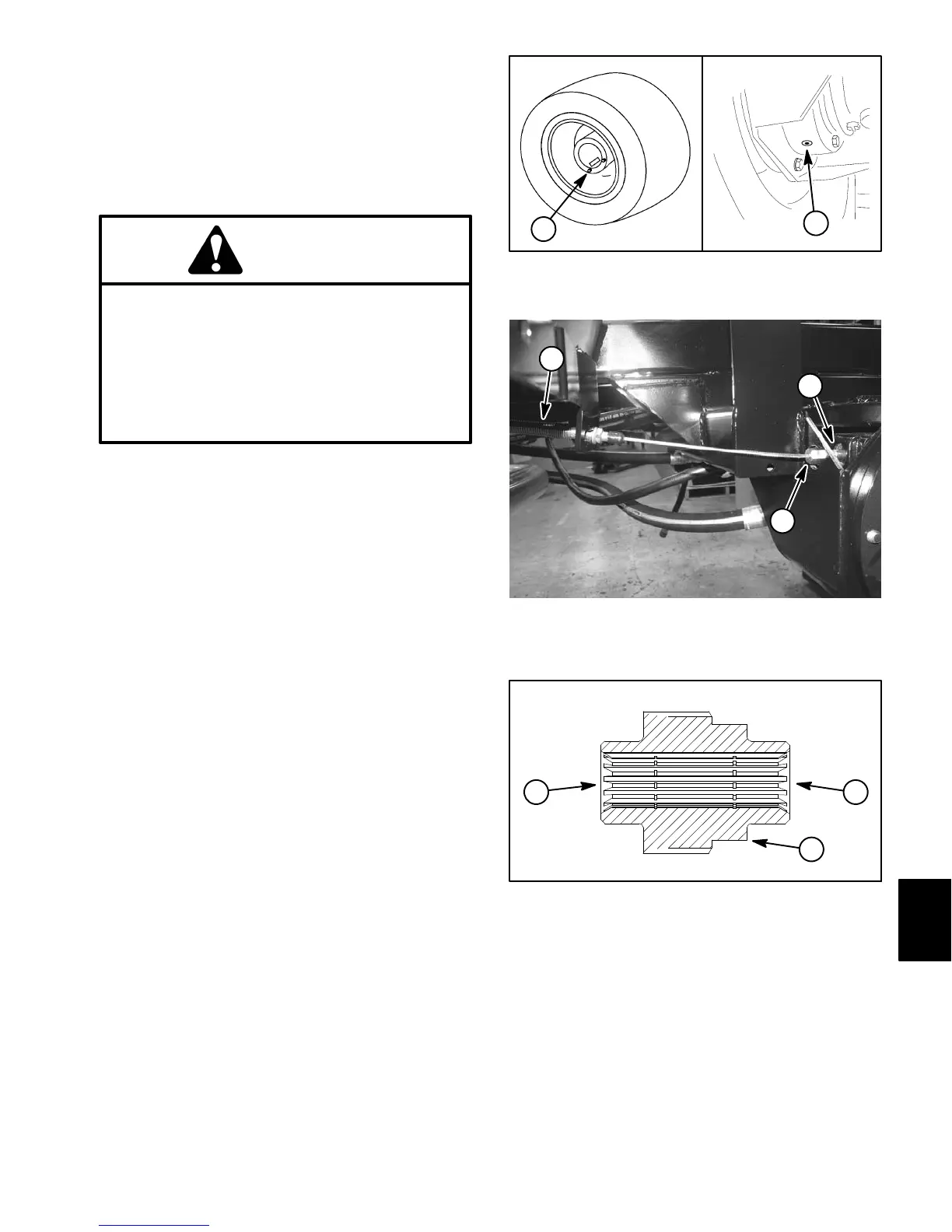
2. Drain oil from planetary wheel drive (Fig. 18A). Drain
oil from brake assembly (Fig. 18B).
CAUTION
Before removing wheels or performing other
service, make sure machine is parked on a sol-
id, level surface such as a concrete floor. Al-
ways chock or block wheels. Use jack stands or
other appropriate load holding devices to sup-
port the raised machine. If the machine is not
properly supported, the machine may move or
fall, which may result in personal injury.
3. Chock front wheels and jack up rear of machine (see
Jacking Instructions in Chapter 1 − Safety in this manu-
al). Support machine with jack stands.
4. Remove rear wheel assembly (see Wheel Assem-
blies in the chapter).
5. Remove hydraulic wheel motor (see Rear Wheel
Motors in Chapter 4 − Hydraulic System in this manual).
Discard O−ring (item 4).
6. Disconnect brake cable from pull rod on brake
(Fig. 19).
NOTE: Be careful to not drop splined brake shaft as
brake assembly is removed.
7. Support brake assembly and remove four (4) flange
head screws (item 6) that secure brake assembly to
planetary assembly. Remove brake assembly and dis-
card gasket (item 3).
8. Locate and remove splined brake shaft (item 8).
9. Complete brake inspection and repair (see Brake In-
spection and Repair in this chapter).
Installation (Fig. 17)
NOTE: The stepped end of the splined brake shaft
must be aligned toward the hydraulic wheel motor
(Fig. 20).
1. Install splined brake shaft into brake assembly. Make
sure that splines engage rotating discs in brake assem-
bly.
AB
1. Planetary drain plug 2. Brake housing drain
Figure 18
1
2
1. Brake cable
2. Brake pull rod
3. Brake cable end
Figure 19
2
1
3
1. Splined brake shaft step
2. Hydraulic motor end
3. Planetary assembly en
Figure 20
2
1
3
Chassis

 Loading...


