Multi Pro 5800 Hydraulic SystemPage 5 − 41
Steering/Boom Lift Circuit − Gear Pump P2 Flow and
Circuit Relief Pressure Test
(Using Tester with Flow Meter and Pressure Gauge)
Over a period of time, the gears and wear plates in the
gear pump can wear. A worn pump will by-pass oil and
make the pump less efficient. Eventually, enough oil can
by-pass to cause circuit performance problems. Contin-
ued operation with a worn, inefficient pump can gener-
ate excessive heat and cause damage to seals and
other components in the hydraulic system.
Gear pump (P2) is designed to satisfy both steering cyl-
inder and lift cylinder needs simultaneously (at full
speed throttle). The Gear Pump (P2) Flow Test com-
pares fluid flow at No Load with fluid flow Under Load.
A drop in flow under load of more than 15% indicates the
gears and wear plates in the pump have worn.
If machine steering is sluggish or otherwise performs
poorly, see Steering/Lift Circuit − Steering Control Valve
and Steering Cylinder Test in this chapter.
If boom lift operation is unsatisfactory, check lift control
manifold solenoid valves and/or lift cylinders. Additional
information on these components is available in this
chapter.
If both steering and lift operations perform poorly, per-
form the gear pump (P2) flow test and circuit relief pres-
sure test (see Steering/Lift Circuit − Relief Pressure Test
in this chapter).
1. Make sure hydraulic oil is at normal operating tem-
perature by operating the machine for approximately ten
(10) minutes. Make sure the hydraulic tank is full.
2. Park machine on a level surface, stop engine, en-
gage parking brake and remove key from the ignition
switch. After turning engine off, operate all hydraulic
controls to relieve hydraulic system pressure.
3. Remove the rear undercarriage shroud (see Under-
carriage Shrouds in Chapter 9 − Chassis in this manual).
CAUTION
Prevent personal injury and/or damage to equip-
ment. Read all WARNINGS, CAUTIONS and Pre-
cautions for Hydraulic Testing at the beginning
of this section.
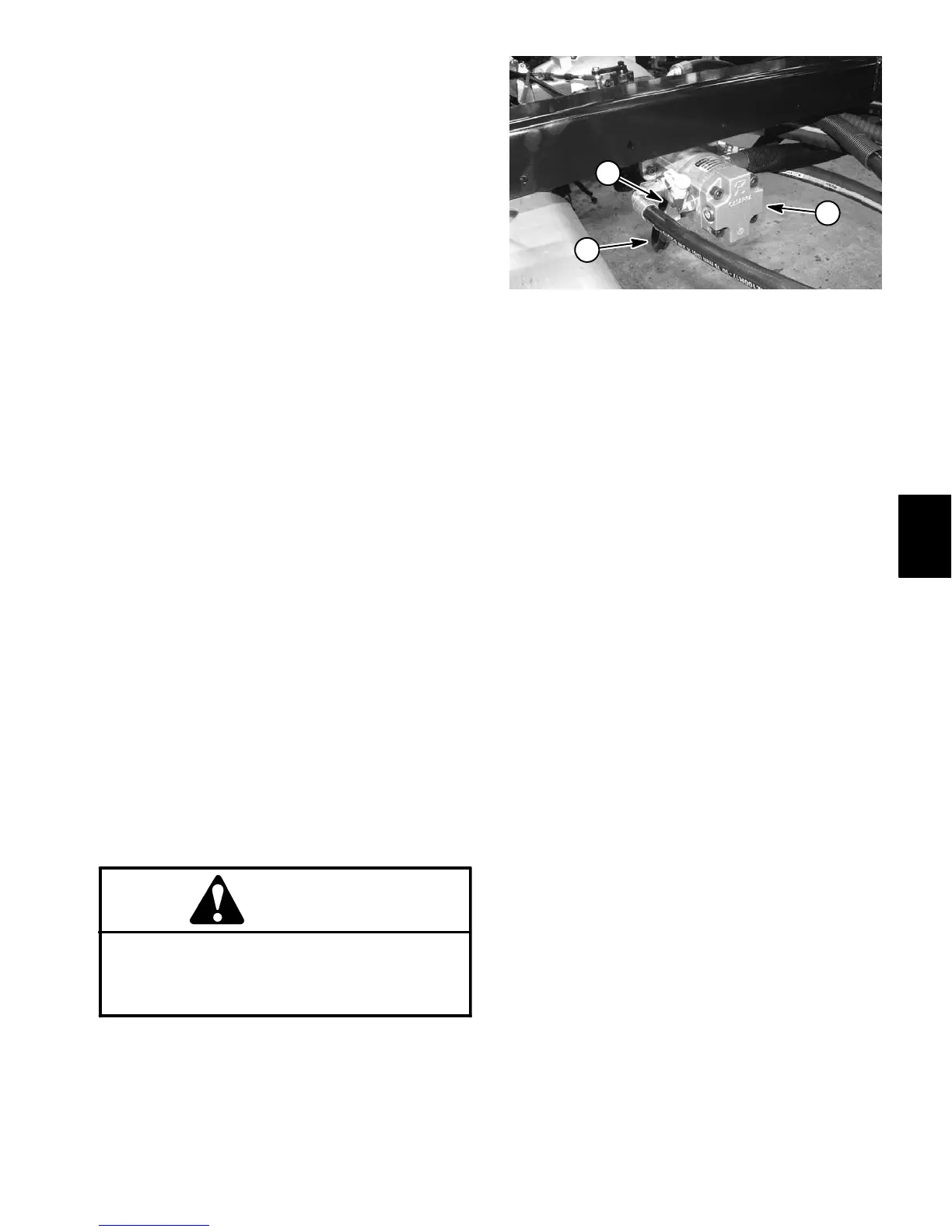
4. Clean tee fitting and hydraulic hose on left side of
rear gear pump section (Fig. 33). Disconnect hydraulic
hose from the tee fitting.
1. Gear pump
2. Steering/boom lift circuit pressure hose
3. Tee fitting (rear gear pump fitting)
Figure 33
2
1
3
IMPORTANT: Make sure that the oil flow indicator
arrow on the flow meter is showing that the oil will
flow from the pump, through the tester and into the
hydraulic hose.
5. Install 15 GPM Hydraulic Tester #TOR214678 (pres-
sure and flow) in series between piston pump fitting and
disconnected hose. Make sure that flow control valve on
tester is fully open.
6. Start engine and run at low idle speed. Check for hy-
draulic leaks and correct before proceeding with test.
7. Operate the engine at high idle speed (Diesel en-
gine = 3050 to 3150 RPM, Gasoline engine = 3200
RPM).
8. Verify pump flow at No Load as follows:
Record tester pressure and flow readings at no load.
Unrestricted pump output should be approximately
4.2 GPM (15.8 LPM).
9. Verify pump flow Under Load as follows:
A. Watch pressure gauge carefully while slowly
closing the flow control valve until 800 PSI (55.2 Bar)
is obtained on gauge.
B. Verify engine speed with a phototac. If engine
speed drops below minimum high idle speed, pump
flow will decrease. Adjust test specifications accord-
ingly (see Testing in this chapter).
C. Record tester pressure and flow readings under
load.
10.Test the pressure relief as follows:
A. With the engine operating at high idle speed, con-
tinue to slowly close the tester flow control valve until
the pressure on gauge stabilizes (continuing to close
Hydraulic
System

 Loading...


