Multi Pro 5800 Hydraulic SystemPage 5 − 59
Disassembly (Fig. 43)
NOTE: Disassemble gear pump for cleaning, inspec-
tion and seal replacement only. If internal components
of pump are worn or damaged, the gear pump must be
replaced as a complete assembly. Individual gears,
housings and thrust plates are not available separately.
The relief valve can be replaced separately.
IMPORTANT: Keep bodies, gears, flanges and
thrust plates for each pump section together; do not
mix parts between pump sections.
1. Plug pump ports and thoroughly clean exterior of
pump with cleaning solvent. Make sure work area is
clean.
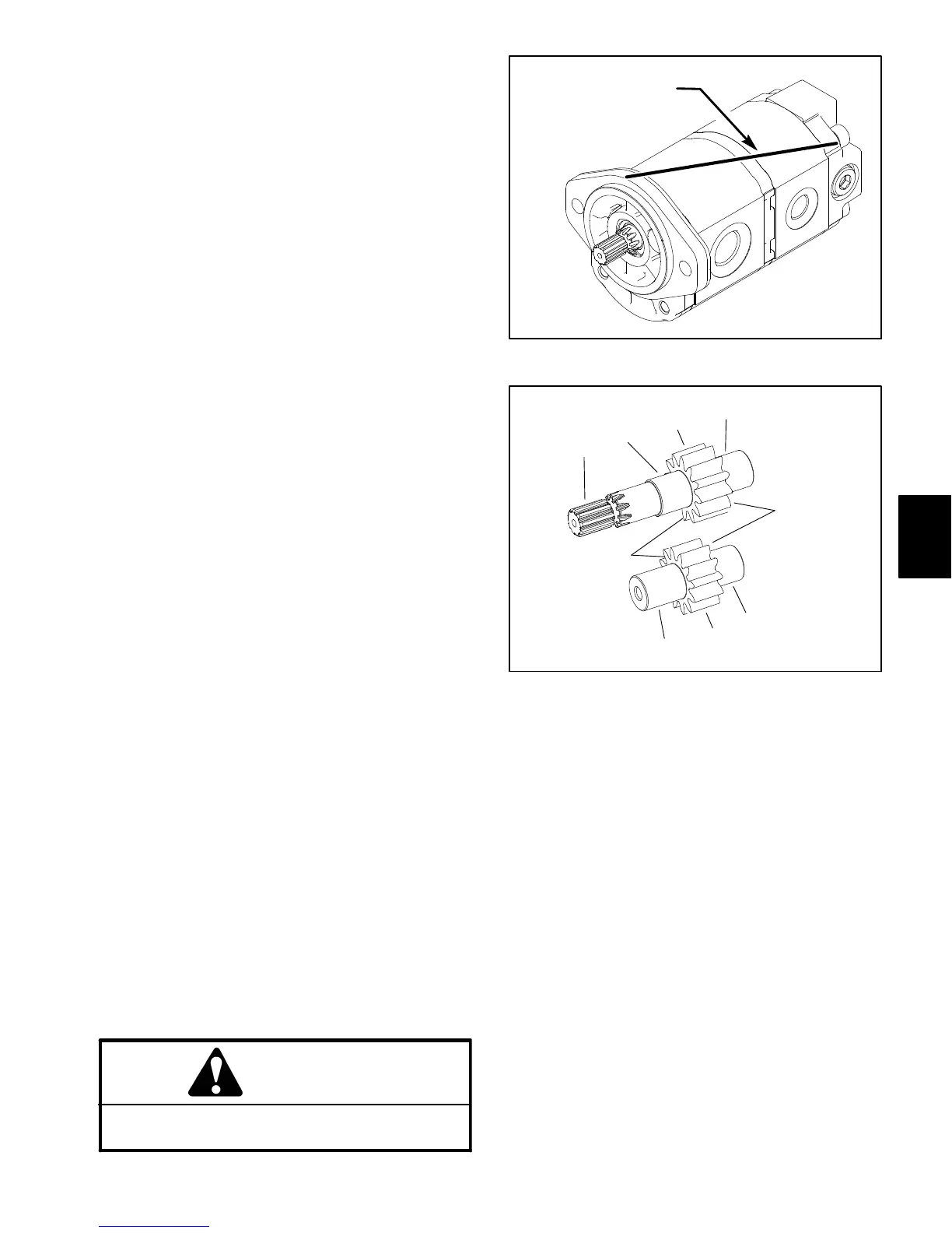
2. Use a marker to make a diagonal line across the
gear pump for assembly purposes (Fig. 44).
IMPORTANT: Use caution when clamping gear
pump in a vise to avoid distorting any pump compo-
nents.
3. Secure the front cover of the pump in a vise with the
drive shaft pointing down.
4. Loosen, but do not remove, the four (4) screws that
secure pump assembly.
5. Remove pump from vise and remove fasteners.
6. Support the pump assembly and gently tap the pump
case with a soft face hammer to loosen the pump sec-
tions. Be careful to not drop parts or disengage gear
mesh.
IMPORTANT: Mark the relative positions of the gear
teeth and the thrust plates so they can be reassem-
bled in the same position. Do not touch the gear sur-
faces as residue on hands may be corrosive to gear
finish.
7. Remove the thrust plates and seals from each pump
section. Before removing each gear set, apply marking
dye to mating teeth to retain ”timing”. Pump efficiency
may be affected if the teeth are not installed in the same
position during assembly. Keep the parts for each pump
section together; do not mix parts between sections.
Gear Pump Inspection
1. Remove any nicks and burrs from all parts with
emery cloth.
CAUTION
Use eye protection such as goggles when using
compressed air.
Figure 44
DIAGONAL LINE
P1
P2
1. Gear shaft spline
2. Gear shaft
3. Gear teeth
4. Gear face edge
Figure 45
3
4
1
2
3
2
2
2
4
2. Clean all parts with solvent. Dry all parts with com-
pressed air.
3. Inspect drive gears and idler gears for the following
(Fig. 45):
A. Gear shafts should be free of rough surfaces and
excessive wear at bushing points and sealing areas.
Scoring, rough surfaces or wear on gear shafts indi-
cates need for replacement.
B. Gear teeth should be free of excessive scoring
and wear. Any broken or nicked gear teeth must be
replaced.
C. Inspect gear face edge for sharpness. Sharp
edges of gears will mill into wear plates and, thus,
must be replaced.
Hydraulic
System

 Loading...


