Multi Pro 5800Hydraulic System Page 5 − 62
Traction (Piston) Pump
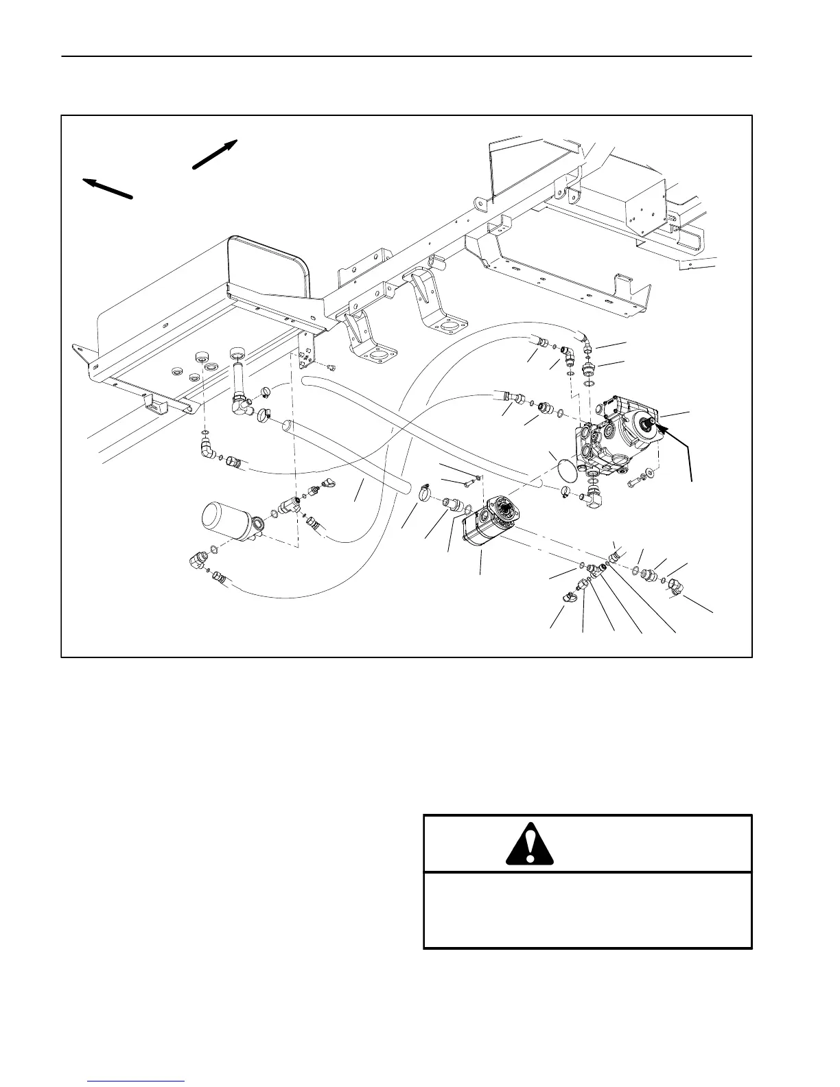
Figure 46
1. Piston (traction) pump
2. O−ring
3. Gear pump
4. Test fitting
5. Hydraulic hose (with cover)
6. Cap screw (2)
7. Flat washer (2)
8. O−ring
9. Hydraulic hose (to steering control)
10. O−ring
11. Hydraulic tee fitting
12. O−ring
13. Hydraulic hose (to pump manifold)
14. Straight fitting
15. O−ring
16. Hose clamp
17. Hydraulic fitting
18. O−ring
19. Dust cap
20. Straight fitting
21. Hydraulic hose
22. Elbow fitting
23. Hydraulic hose
24. Straight fitting
25. Hydraulic hose
VIEWED FROM
BOTTOM OF MACHINE
FRONT
RIGHT
2
3
6
8
9
10
11
13
1
5
7
12
14
15
16
17
18
19 4
12
ANTI−SEIZE
LUBRICANT
23
20
21
22
24
25
Removal (Fig. 46)
1. Park machine on a level surface, stop engine, en-
gage parking brake and remove key from the ignition
switch.
2. Remove the rear undercarriage shroud (see Under-
carriage Shrouds in Chapter 9 − Chassis in this manual).
3. To prevent contamination of hydraulic system during
pump removal, thoroughly clean exterior of pump as-
sembly.
CAUTION
Rotate steering wheel and depress traction ped-
al in both forward and reverse to relieve hydrau-
lic system pressure and to avoid injury from
pressurized hydraulic oil.
4. Operate all hydraulic controls to relieve hydraulic
system pressure.

 Loading...


