Multi Pro 5800Page 7 − 38ExcelaRate Spray System
15.Using marks made during disassembly to identify
connecting rod locations, install connecting rods to
crankshaft. Makes sure that connecting rod flange fits
under connecting rod spacers.
16.Place second connecting rod spacer onto crankshaft
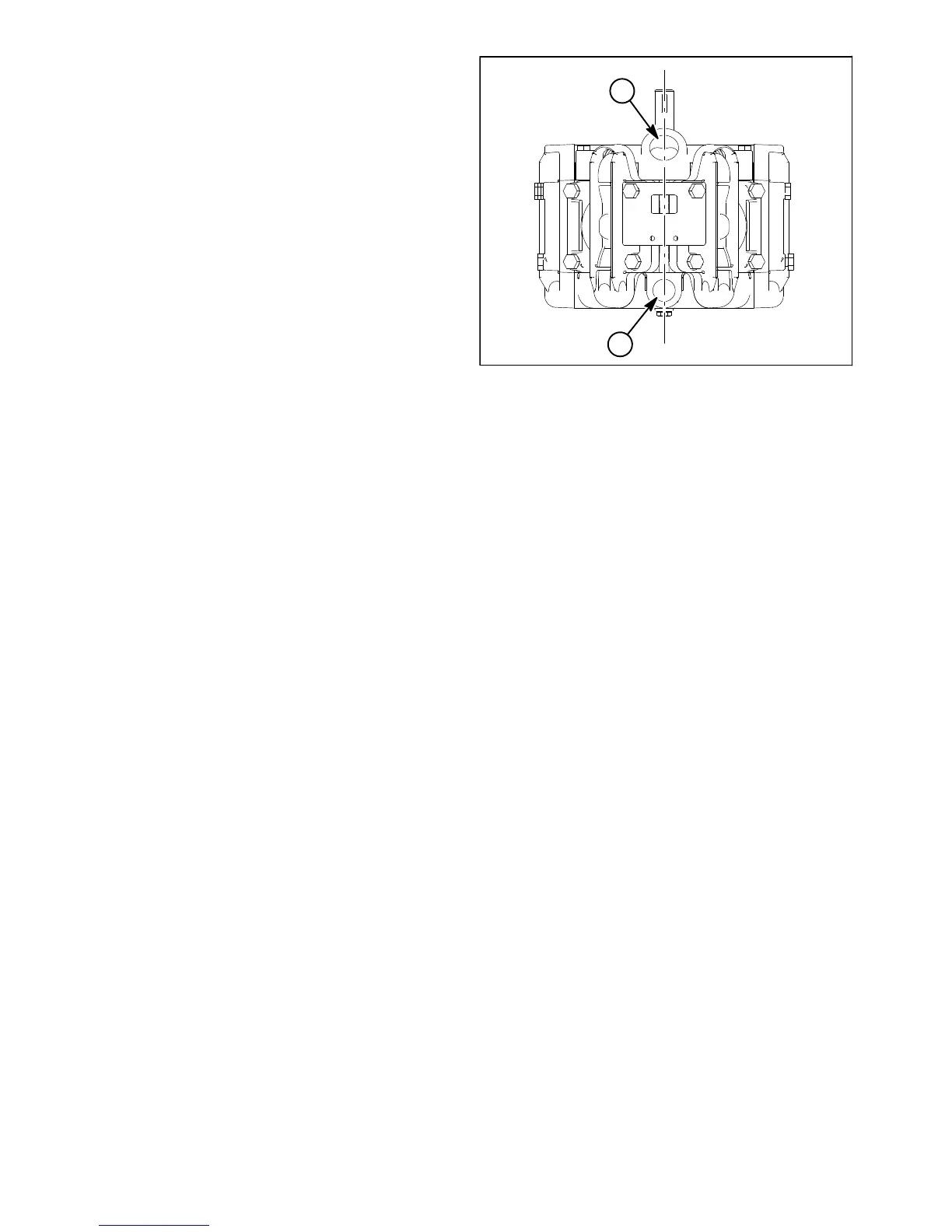
and connecting rods and then install pump casting (suc-
tion). Make sure that pump suction and outlet ports are
aligned during assembly of the pump castings (Fig. 36).
17.Secure pump castings with three (3) hex bolts. Tight-
en bolts from 60 to 72 ft−lb (82 to 97 N−m). After as-
sembly, check that crankshaft turns freely.
Assembly
1. Install diaphragms to connecting rods:
A. Place diaphragm backing disc (item 7), new dia-
phragm (item 6) and diaphragm disc (item 5) on con-
necting rod. Make sure that the diaphragm disc lip
faces away from the diaphragm.
B. Thread hex bolt (item 4) into connecting rod.
C. Rotate crankshaft so the connecting rod is at the
top of its stoke and tighten the hex bolt from 60 to 72
ft−lb (82 to 97 N−m).
D. Repeat for remaining diaphragms.
2. Install valves and valve covers:
IMPORTANT: For model 363 pumps only, the two (2)
pump inlet valves in the upper head positions
(either side of suction port) are different than the
rest of the valves used in the pump (item 23 Fig. 34).
These two (2) valves are white in color.
A. Position new O−rings and valves (suction and
outlet) to pump castings. Suction valves should be
installed with the spring up. Outlet valves should be
installed with the spring down into the pump casting.
B. Place valve cover over valves noting orientation
of cover inlet and outlet. Make sure that diaphragm
lip, valves and O−rings fit into recesses in cover.
NOTE: Pump bracket on model 363 pumps (item 26
Fig. 34) is secured to pump with two (2) longer bolts on
upper valve covers. Pump foot for both model 363 and
364 pumps (item 16) is secured to pump with four (4)
longer bolts on lower valve covers.
C. Secure valve cover to pump using hex bolts (4 per
cover) and tighten bolts from 60 to 72 ft−lb (82 to 97
N−m).
D. Repeat for remaining valve covers.
1. Suction port 2. Outlet port
Figure 36
2
1

 Loading...


