Multi Pro 5800 Page 7 − 63 ExcelaRate Spray System
Assembly (Fig. 57)
NOTE: Replace, do not reuse gaskets and O−rings.
Coat O−rings and gaskets with vegetable oil or silicone
grease before installation to reduce damage during as-
sembly.
1. If pivot bracket (item 4) was removed from machine:
A. Lightly lubricate bushings (item 6) with motor oil
before assembly.
B. Install pivot pin (item 12) from rear of machine.
C. Connect boom lift cylinder (not shown) to pivot
bracket (see Boom Lift Cylinders in Chapter 4 − Hy-
draulic System in this manual).
2. Make sure that hinges (item 5) are securely fastened
to pivot bracket (item 4) and spray boom (item 20). The
boom hinge uses four (4) backing plates (item 13) be-
tween the spray boom and flange nuts.
3. Position boom hinge to pivot bracket hinge. Make
sure that rubber boots (item 18) are placed at hinge
junctions and that ribs on boots are toward the top of the
boom (Fig. 58).
4. Insert two (2) cap screws (item 10) through flat wash-
ers (item 9) and hinges. Place dampener (item 19),
breakaway spring (item 16), spring retainer (item 15)
and lock nut (item 11) on each cap screw. Make sure that
shoulder on spring retainer fits into breakaway spring.
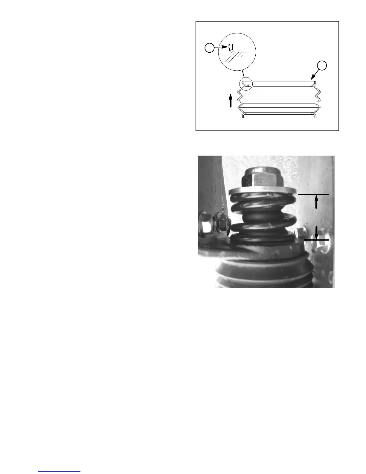
5. Tighten lock nuts to obtain a compressed spring
height of 1.53 to 1.59” (39 to 40 mm) (Fig. 59).
6. Connect boom supply hose to boom section valve.
7. Secure boom supply hose to center boom with
clamps and ties as recorded during disassembly.
8. Lubricate grease fittings on boom hinge.
1. Rubber boot 2. Rib
Figure 58
UP
1
2
Figure 59
1.53 to 1.59”
(39 to 40 mm)

 Loading...


