Multi Pro 5800Page 8 − 62GeoLink Spray System
Installation (Fig. 69)
1. If valve bracket or agitation throttle valve was re-
moved, install items with fasteners previously removed.
2. If suction and/or outlet fittings were removed from
pump:
A. Model 363 spray pumps use non−O−ring style
suction and outlet fittings. Apply thread sealant to fit-
ting threads and install fitting(s) into correct pump
port (Fig. 71).
B. Model 364 spray pumps use O−ring style suction
and outlet fittings. Coat new O−ring with vegetable
oil and install fitting(s) into correct pump port
(Fig. 71).
NOTE: Replace, do not reuse O−rings. Coat all O−
rings with vegetable oil before installation to reduce the
chance of damage during assembly.
3. If suction hose was removed from pump suction fit-
ting, secure the suction hose assembly to the pump be-
fore the pump is installed to the machine. Install suction
hose assembly and secure with fork.
4. Install woodruff key into pump shaft and apply anti-
seize lubricant to inside of coupler (item 14) pump shaft
and key.
CAUTION
To prevent personal injury, make sure that pump
is properly supported as it is installed to the ma-
chine. Pump assembly weighs approximately
125 pounds (57 kg).
5. Place pump assembly (Fig. 71) onto pump bracket.
Align pump shaft and key with coupler and slide pump
shaft into coupler.
6. Install and finger tighten four (4) flange head screws
(item 2) and flange nuts to attach pump assembly to
pump bracket. DO NOT fully tighten fasteners at this
time.
7. Turn spray pump shaft by hand and position pump on
pump bracket to best align the pump shaft and the hy-
draulic motor shaft.
8. Secure pump to pump bracket by tightening flange
head screws and flange nuts.
1
2
3
4
5
6
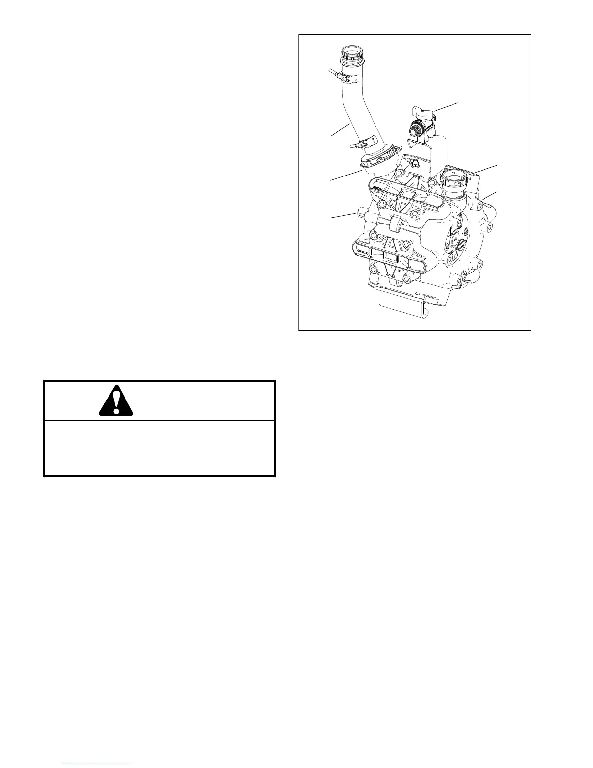
1. Spray pump
(model 364 shown)
2. Pump shaft
3. Fitting (outlet)
4. Agitation throttle valve
5. Fitting (suction)
6. Hose (suction)
Figure 71
9. Apply medium strength thread locker to coupler set
screws (item 13). then install and tighten set screws to
secure coupler to pump shaft.
10.Position pump shaft guard over hydraulic motor
mounting screws. Tighten flange head screws and
flange nuts to secure control manifold/motor assembly
to motor mount plate.
11.If present, install clamp (item 25) to valve bracket
and secure with flat washer and cap screw previously re-
moved.
12.Connect spray pump suction and supply hoses to
spray pump and secure with forks (Fig. 70).
13.Connect hoses to agitation throttle valve (item 26)
and secure hoses with forks.
14.Check spray system for leaks. Repair all leaks be-
fore returning the sprayer to service.

 Loading...


