Multi Pro 5800 ChassisPage 9 − 13
Removal (Fig. 8)
1. Park machine on a level surface, stop engine, en-
gage parking brake and remove key from the ignition
switch.
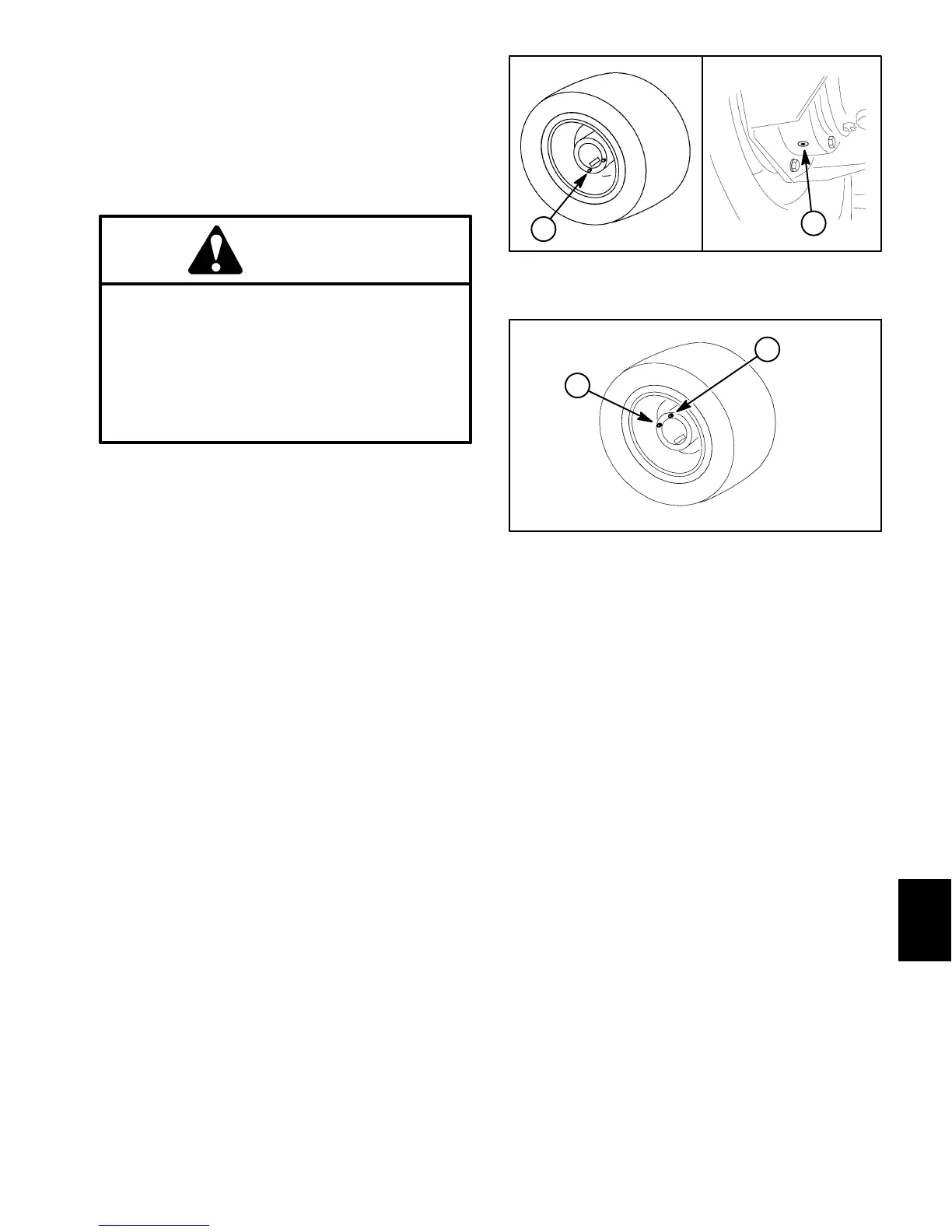
2. Drain oil from brake assembly (Fig. 9A). Drain oil
from planetary drive (Fig. 9B).
CAUTION
Before removing wheels or performing other
service, make sure machine is parked on a sol-
id, level surface such as a concrete floor. Al-
ways chock or block wheels. Use jack stands or
other appropriate load holding devices to sup-
port the raised machine. If the machine is not
properly supported, the machine may move or
fall, which may result in personal injury.
3. Chock front wheels and jack up rear of machine (see
Jacking Instructions in Chapter 1 − Safety in this manu-
al). Support machine with jack stands.
4. Remove rear wheel assembly (see Wheel Assem-
blies in the chapter).
5. Support wheel motor and brake assembly to prevent
them from shifting during planetary removal.
NOTE: The wheel motor and brake assembly fasteners
thread into the planetary housing, and must be removed
prior to removing the planetary drive from the machine.
6. Remove two (2) cap screws and flat washers that se-
cure wheel motor to planetary assembly. Check condi-
tion of O−ring (item 4) and replace if necessary (see
wheel motors in Chapter 5 − Hydraulic System in this
manual).
7. Remove four (4) flange head screws that secure
brake assembly to planetary assembly (see Brake As-
sembly in this chapter). Remove and discard gasket
(item 3).
8. Support planetary assembly to prevent it from falling.
Loosen and remove eight (8) flange head screws that
secure planetary assembly to frame. Remove planetary
assembly from machine.
Installation (Fig. 8)
1. Make sure that gasket surfaces of planetary and
brake assembly are clean. Position new gasket (item 3)
to brake assembly.
1. Planetary drain plug 2. Brake housing drain
Figure 9
1
2
AB
1. Planetary check plug 2. Fill plug
Figure 10
1
2
2. Position planetary assembly to machine making
sure to engage splined brake shaft with planetary drive
shaft. Secure planetary assembly to frame with eight (8)
flange head screws. Tighten screws from 60 ft−lb
(81 N−m).
3. Make sure gasket (item 3) is properly aligned and se-
cure brake assembly to planetary (see Brake Assembly
in this section of this chapter). Tighten screws from 60
ft−lb (81 N−m).
4. Make sure wheel motor O−ring (item 4) is in position
and secure wheel motor to planetary with two (2) cap
screws and flat washers. Tighten screws from 60 ft−lb
(81 N−m).
5. Install rear wheel assembly (see Wheel Assemblies
in this chapter).
6. Make sure brake housing drain plug is installed and
position wheel as shown (Fig. 10). Fill planetary wheel
drive with SAE 85W−140 gear lube to level of check
plug. Capacity is approximately 18 to 20 fl oz (0.53 to
0.59 L) per drive. A portion of the gear lube will pass into
the brake assembly automatically. Install planetary drive
plugs.
7. Check and adjust brake cables for proper brake op-
eration (see machine Operator’s Manual).
8. Remove jack stands and lower machine to ground.
Chassis

 Loading...


