Corrective Maintenance
Printhead Pressure Dials
204
14207L-001 A ZM400/ZM600 Maintenance Manual 8/9/07
5. Reinstall the lower latch screw.
6. See Figure 72 on page 201. Connect the printhead cables to the printhead fork assembly.
Lift the assembly and carefully slide the assembly into the print mechanism, ensuring the
data cable and power cable are kept away from the printhead lifting spring (see Figure 73
on page 202).
7. Route the printhead cables over the top of the wire guide.
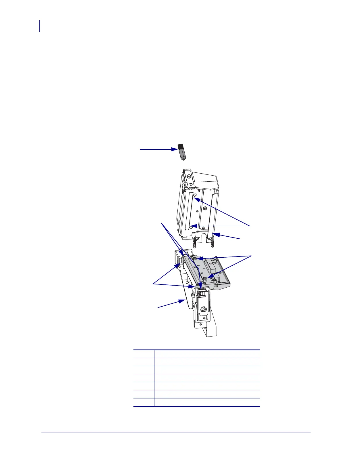
8. See Figure 76. Align the two alignment pins on the printhead with the two alignment holes
in the print mechanism.
Figure 76 • Align the Forks and Bearings
1
Thumbscrew
2
Alignment holes
3
Wire guide
4
Alignment pins
5
Platen housing
6
Forks (2)
7
Bearings (2)
5
7
2
4
6
1
3
 Loading...