EasyManuals Logo

Allied Telesis SwitchBlade x3100 Series User Manual

Allied Telesis SwitchBlade x3100 Series
940 pages
To Next Page IconTo Next Page
To Previous Page IconTo Previous Page
Page #32 background imageLoading...
Page #32 background image
Introduction Card Configurations
Software Reference for SwitchBlade x3100 Series Switches (Setting Up the Switch)
1-2
1.2 Chassis Configuration
1.2.1 Card Configurations
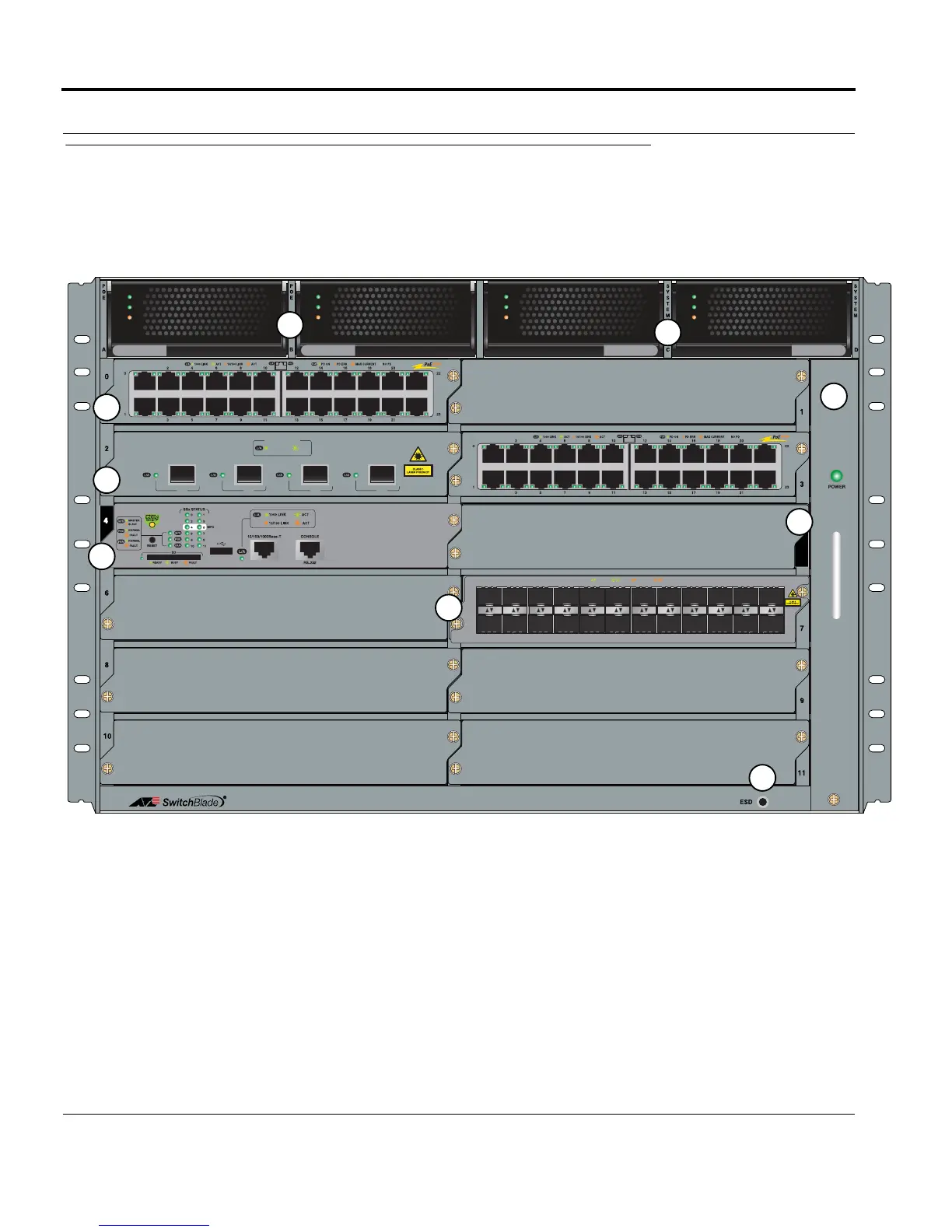
The following figure shows the card layout of the SBx3112 and has labels that are explained in TABLE 1-1.
FIGURE 1-1 SBx3112 Chassis
5
SBx31GP24
AC
DC
FAULT
SBx3165
SBx3161
AC
DC
FAULT
SBx3161
AC
DC
FAULT
AC
DC
FAULT
SBx3165
SBx3112
10G LINK
PORT ACTIVITY
ACT
XFP
0
XFP
1
XFP
2
XFP
3
SBx31XZ4
SBx31GP24
SBx31GP24
SBx31FAN
F
E
D
A
A
C
SBx31GS24
357911
2 4 6 8 10 12 14 16 18 20
22
13 15 17 19 21
23
0
1
1000 LINKACT10/100 LINK ACT
A
B
SBx31CFC
B

Table of Contents

Questions and Answers:

Question and Answer IconNeed help?

Do you have a question about the Allied Telesis SwitchBlade x3100 Series and is the answer not in the manual?

Allied Telesis SwitchBlade x3100 Series Specifications

General IconGeneral
BrandAllied Telesis
ModelSwitchBlade x3100 Series
CategorySwitch
LanguageEnglish

Related product manuals