EPSR Protocol Introduction
4-119
Software Reference for SwitchBlade x3100 Series Switches (Layer Two Switching)
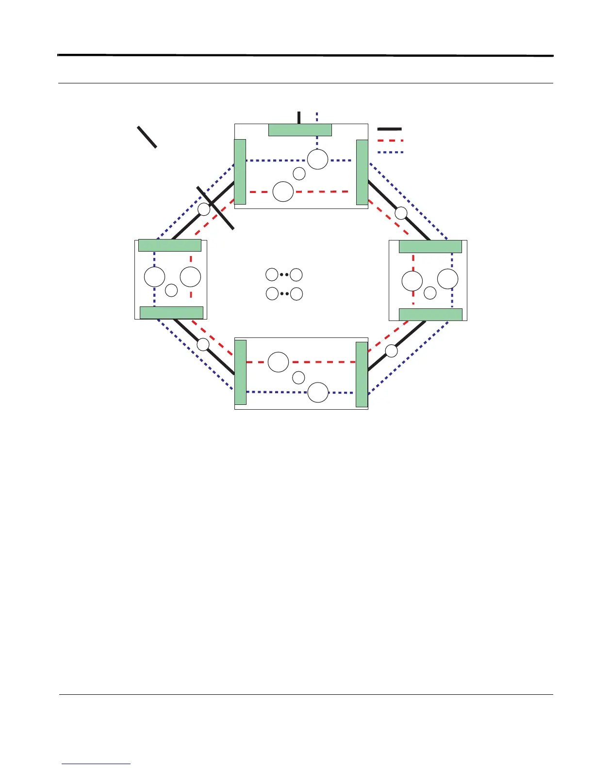
FIGURE 4-10 An EPSR stabilized Network after Ring Fault (Standard VLAN)
4.6.4.5 Master Node Fault Restoration Procedure
When the fault in the ring between Allied Telesis System A and Allied Telesis System B is fixed, the polling EPSR
Health control message that was being sent by the master node over its PP port (sent even when the fault is
present) is now received over its SP port. The master node then takes the following actions to restore the ring
back from that shown in Figure 4-10 to its original normally operating state.
1. Declares the EPSR domain to be in a complete state from the failed state it was in before the fault was
corrected.
2. Blocks its SP port for non-control VLAN traffic for this EPSR domain.
3. Flushes its own forwarding database (FDB) for the two ring ports.
4. Sends an EPSR Ring-Up-Flush-FDB control message to all the transit nodes via both its PP port and SP port.
As the EPSR domain non-control traffic starts flowing again, all nodes (both master and transit) then re-learn
the layer 2 addresses again to reflect the newly collapsed network topology. The master node continues to fol-
= Data VLAN (V_80)
= Physical Link
A
D
= Devices
= Links
V_60
V_80
V_80
V_60
V_80 V_60
B
C
B
1
2
3
4
1
4
V_80
V_60
2.1
A
= Control VLAN (V_60)
= Physical Link 1
is blocked, so Device
A and B report break
to Master Node C
0.1
1.2
1.1
0.2
1.1
0.1
0.2
1.1
PP
SP
Master
Node
Data VLAN is
unblocked
To / From Network
EPSR_Topology_50_Post_Fault
D

 Loading...


