Introduction STP Configuration with UFO VLAN
Software Reference for SwitchBlade x3100 Series Switches (Layer Two Switching)
4-168
4.7.4 STP Configuration with UFO VLAN
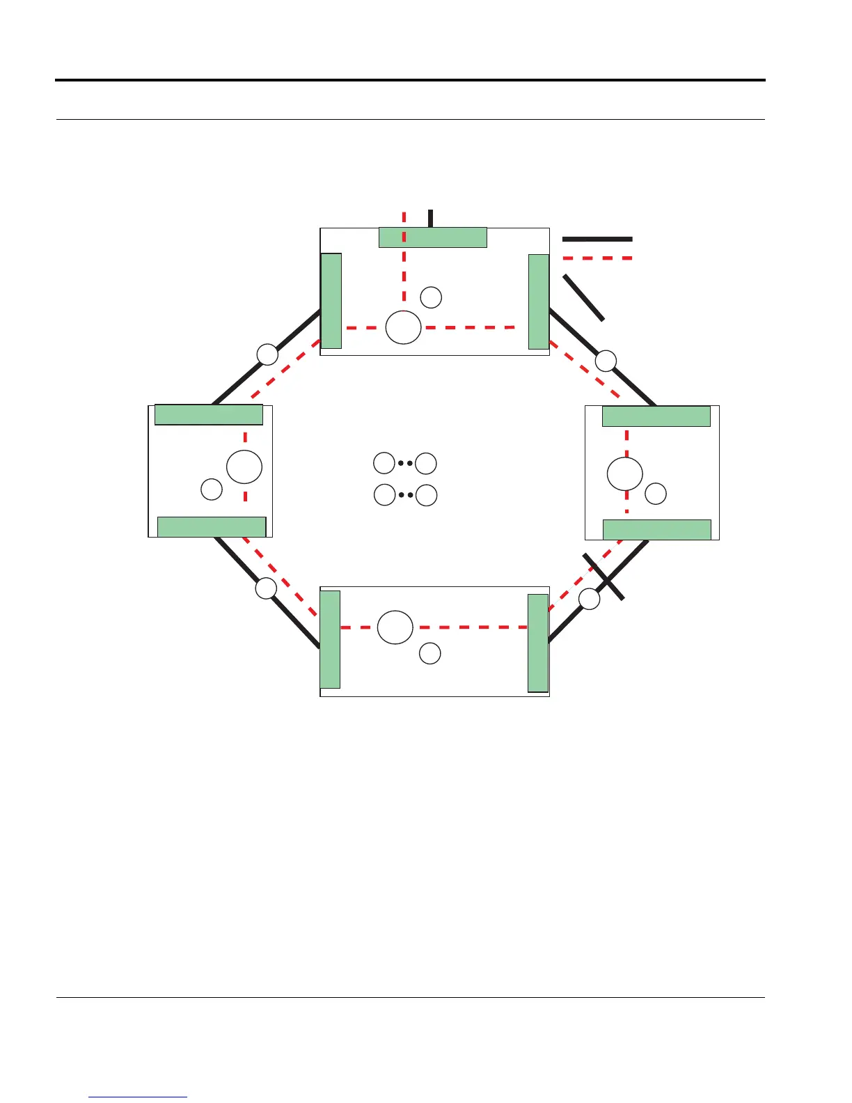
Figure 4-20. shows an example ring configuration that uses (R)STP with UFO VLANs
FIGURE 4-20 Ring Topology Using STP and UFO VLAN
Once the topology stabilizes, in each system one of the ports will become the root port (the one closest to the
root bridge as determined by STP) and the other port(s) become the designated port. The port which is the
root port is considered to be the upstream port and the port which is not the root port (designated port) is
considered to be the downstream port.
The user can provision the ports in each shelf with
FORWARDING=STP indicating that the topology is a ring and
allowing the STP protocol to determine the exact upstream.
To prevent one of the systems from becoming the Spanning Tree root bridge, the network design must ensure
that the appropriate STP parameters are set such that the root bridge is always located above the ring configu-
ration made up of the systems.
= Physical Link
A
D
= Devices
= Links
V_60
V_60
V_60
B
C
1
2
3
4
1
4
V_60
D
0.3
A
= VLAN 60 (V_60)
0.1
0.2
0.1
0.2
0.2
0.1
0.2
0.1
= STP Blocking of Physical Link
To / From Network
Ring_Topology_STP_60
Upstream
Upstream
Downstream
Upstream
Downstream
Downstream
If Device A is the root, UFO VLAN is set at interfaces:
0.1 = DOWNSTREAM
0.2 = DOWNSTREAM
0.3 = PRIMARYUPSTREAM
If Device A is not the root, VLAN is set at STP at all
three interfaces
For other devices, UFO VLAN on the interface
set to STP for dynamic state change
(Upstream to Downstream,
Downstream to Upstream)

 Loading...


