Introduction MSTP Configuration with UFO VLAN
Software Reference for SwitchBlade x3100 Series Switches (Layer Two Switching)
4-170
4.7.5 MSTP Configuration with UFO VLAN
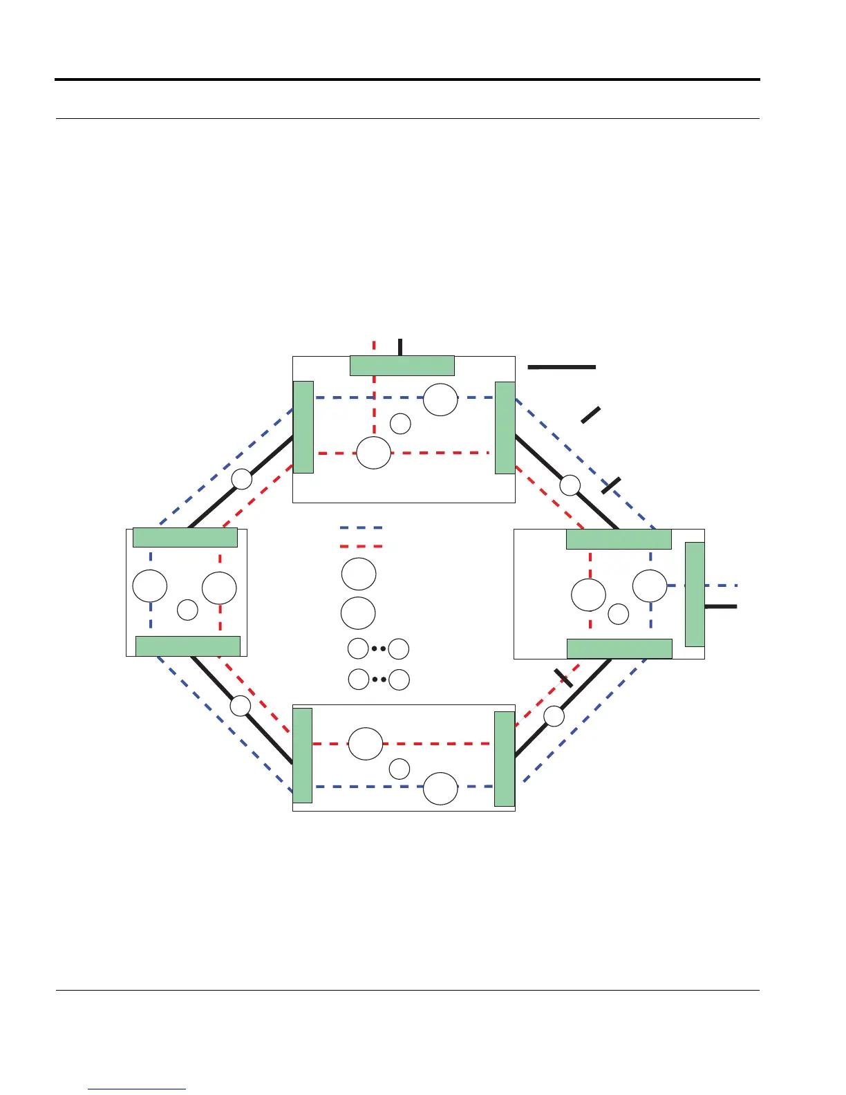
Figure 4-21 shows an example configuration that uses MSTP with UFO VLANs.
Parameters can be set so that each MSTI has a Regional Root Bridge on separate systems. On each of these
systems, the VLANs on the upstream port are set to PRIMARYUPSTREAM and the other ports are set to
DOWNSTREAM. All other ports are other systems are set to STP.
Note: In this example, each MST Instance has only one VLAN and its upstream interface is configured as
PRIMARYUPSTREAM. If there are multiple VLANs for an MST Instance, each VLAN should be set as
PRIMARYUPSTREAM over the same upstream port.
FIGURE 4-21 Ring Topology Using MSTP and UFO VLAN
= Physical Link
A
D
= Devices
= UFO VLAN 60
MST1 Instance
= UFO VLAN 80
= Links
V_60
V_60
MST2 Instance
V_80
V_80
V_60
V_80 V_80
V_80
B
C
1
2
3
4
1
4
V_60
V_60
D
0.3
0.3
A
0.1
0.2
0.1
0.2
0.2
0.1
0.2
0.1
= Blocking of VLAN trac
To / From Network
To / From
Network
For Root Bridge A,
UFO VLANS set as
0.1 = DOWNSTREAM
0.2 = DOWNSTREAM
0.3 = PRIMARYUPSTREAM
For other devices, UFO VLAN
on the interface set to STP
for dynamic state change
For Root Bridge D,
UFO VLANS set as
0.1 = DOWNSTREAM
0.2 = DOWNSTREAM
0.3 = PRIMARYUPSTREAM
For other devices, UFO VLAN
on the interface set to STP
for dynamic state change
Regional Root Bridge MST2
Regional
Root Bridge
MST1

 Loading...


