Introduction UCP with EPSR/RSTP
Software Reference for SwitchBlade x3100 Series Switches (Layer Two Switching)
4-178
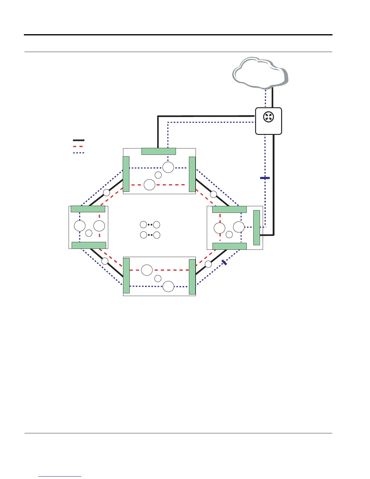
FIGURE 4-23 EPSR Topology with UCP
4.8.4.1 Fault Message and Recovery - Physical Link
Assume a fault occurs on link 2. The EPSR protocol reacts and takes steps to change the topology so that no
node is isolated and no new loops are formed. The UPC protocol makes sure that the direction of the ports
(upstream, downstream) are set correctly.
On node C, the UCP protocol sends the Upstream Port Topology Change (4.8.2.2) message for the UFO
VLAN. This message is received and forwarded to the next node until the node that receives the message is the
upstream node (A). Therefore, nodes D and A would receive the message.
= Data VLAN (600)
= Physical Link
A
D
= Devices
= Links
1200
600
600
1200
600 1200
B
C
1
2
3
4
1
4
600
1200
D
10.0
A
= Control VLAN (1200)
= data VLAN is blocked
over Physical Link 3
UPC is part of VLAN
messaging and so it
is blocked
11.2
10.1
10.1
10.2
11.2
10.1
10.1
10.2
PP
SP
Master
Node
10.0
Primary
Upstream
Interface
Secondary
Upstream
Interface
UP
UP
DOWN
DOWN
DOWN
UP
DOWN
DOWN
EPSR_UCP_Interop
Upstream Network
SBx900

 Loading...


