EPSR Terms and Definitions Introduction
4-115
Software Reference for SwitchBlade x3100 Series Switches (Layer Two Switching)
vlan traffic is not blocked at the SP port and is allowed to flow through. This does not pose a problem, because
the control messages originate either at a master node or transit node but always terminate at the master node.
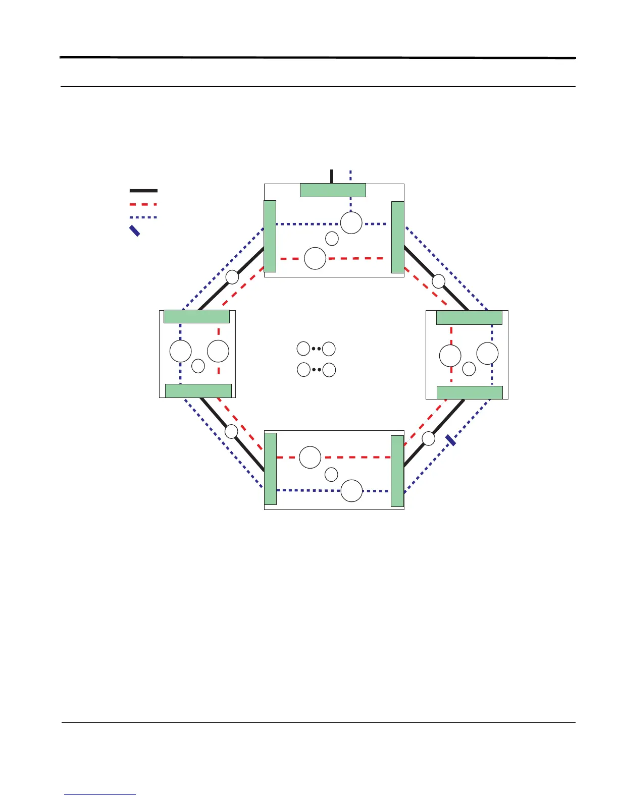
The ring network when stabilized collapses to what is shown in Figure 4-9 below:
FIGURE 4-9 An EPSR Ring Topology (Standard VLAN)
When the master node detects a physical link break in the ring, it unblocks its SP port and allows the flow of
non-control traffic through EPSR domain. This mode continues until the master node determines that the break
in the ring has been restored; at which point, it goes back to its normal operating procedure.
4.6.3 EPSR Terms and Definitions
To implement EPSR, the user is required to configure the EPSR protocol to support the fault detection and
recovery in the network. Configuration data is as follows:
• Hello Time
= Data VLAN (V_80)
= Physical Link
A
D
= Devices
= Links
V_60
V_80
V_80
V_60
V_80 V_60
C
1
2
3
4
1
4
V_80
V_60
2.1
A
= Control VLAN (V_60)
= data VLAN is blocked
over Physical Link 3
0.1
1.2
1.1
0.2
1.1
0.1
0.2
1.1
PP SP
Master
Node
To / From Network
EPSR_Topology__non_UFO
B
D

 Loading...


