Introduction Possible Fault Scenarios
Software Reference for SwitchBlade x3100 Series Switches (Network Management)
7-120
- “BFD Detected mis-wiring” (failing, severity as appropriate for the interface)
• For detection that the system has not received BFD packets within the interval times the detection multi-
plier. The alarm is as follows:
- “BFD Session Failed” (failing, severity as appropriate for the interface)
• For detection that the remote peer is reporting (in the State field received in the remote’s packets) that the
remote BFD State is down. The alarm is as follows:
- “Remote BFD Session Failed” (failing, severity as appropriate for the interface)
The treatment of the failures reported via BFD will be subject to OAM’s special debounce treatment of failures
for Ethernet interfaces:
• The first raise and clear of an alarm is reported immediately (no soak).
• If a second raise and clear of an alarm on that same interface is declared before a 15 second timer expires,
then the raise is processed immediately, but the clear will not be reported (soaked) for 10 seconds.
7.7.4 Possible Fault Scenarios
There are situations, described below, in which packets are not being exchanged between two 802.3 MACs but the nor-
mal physical layer fault detection (such as LOL or LOF) does not report the failure. Once the failure has been
reported by BFD, it is treated as a physical link failure and topology features (such as RSTP) are activated to
restore network connectivity. Following are some examples where this could occur.
7.7.4.1 BFD with a DS3 Configuration
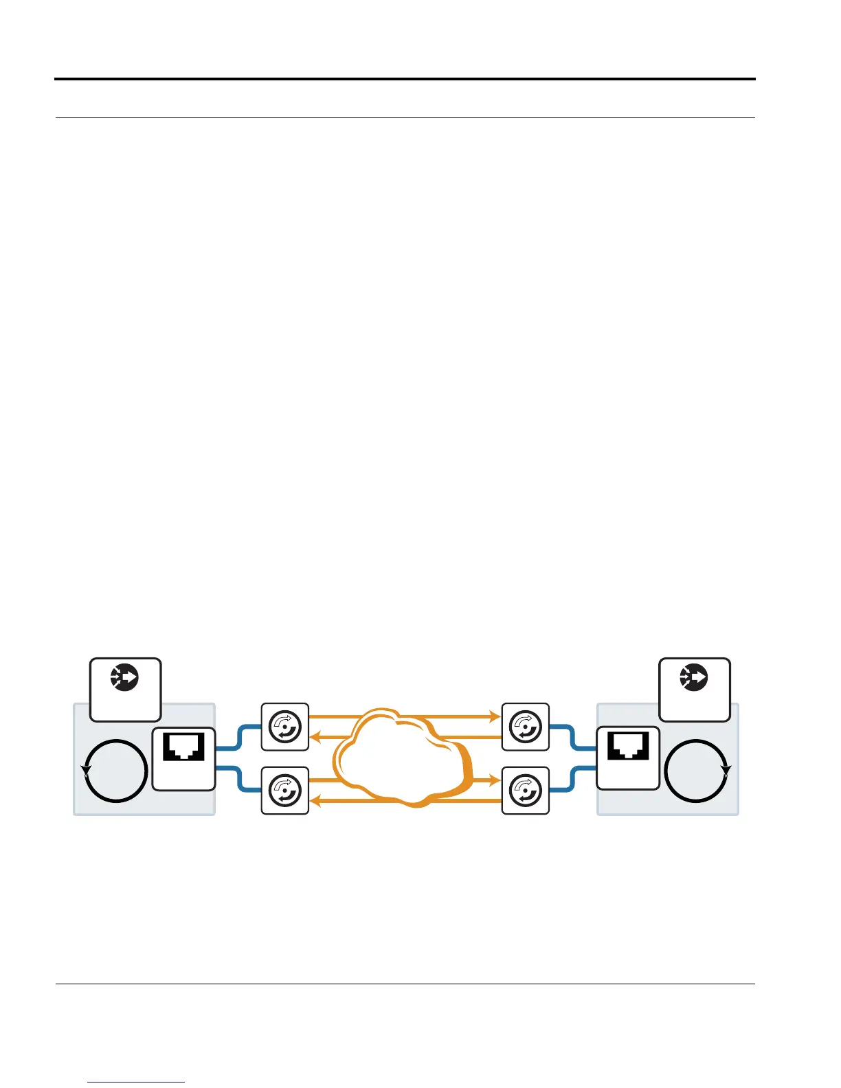
One example in which this can occur is when Network Access products are connected using DS3 facilities,
with RSTP selecting which FE port is forwarding packets. Refer to the following figure.
FIGURE 7-16 Network Access Products Connected using the TN-1000 (no faults)
RSTP
DS3_Connection_3112
DS3 Module DS3 Module
DS3 Module DS3 Module
DS3
Network
1.0
2.0
1.0
2.0
RSTP
SBx3100
SBx3112
SBx3100
SBx3112
GE
GE

 Loading...


