Multiple Spanning Tree Protocol (MSTP) Introduction
4-79
Software Reference for SwitchBlade x3100 Series Switches (Layer Two Switching)
Note: Each VLAN can be associated with only one instance.
Bridges that share a common set of MSTIs (each with their associated set of VLANS) make up an MST region,
with each MSTI forming a logical network topology; this is explained below.
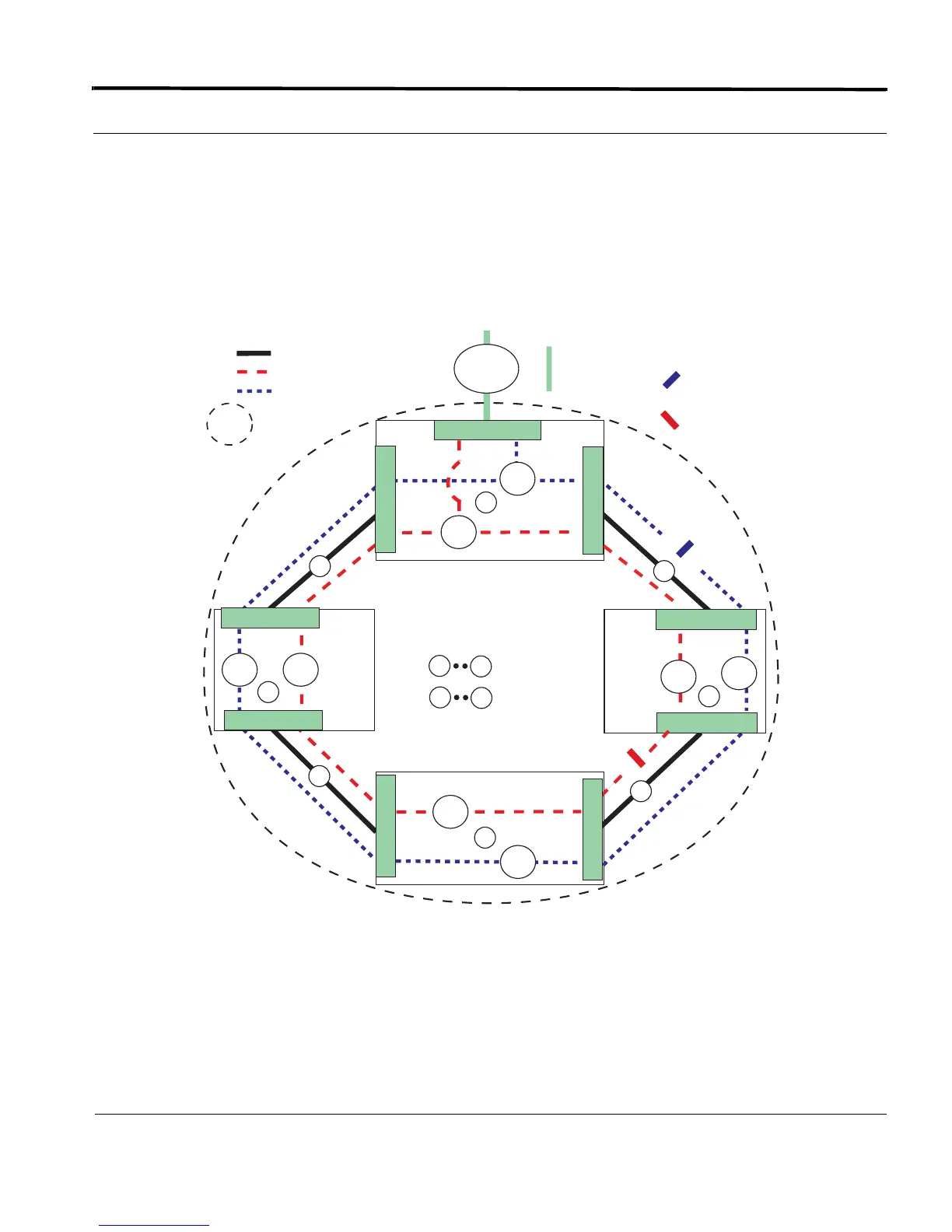
Figure 4-6 shows an example of a network using MSTP. Note that the CIST has been omitted for simplicity.
Note: Since MSTP is a set of RSTP instances, the user should be familiar with the concepts of the single
(R)STP instance, explained in previous subsections.
FIGURE 4-6 Concept of an MSTP Network
In Figure 4-6, there are two MST instances, Instance 1 with VLAN 60 and Instance 2 which includes VLAN 80.
Only one VLAN is associated with each instance; more than one VLAN can be associated with an MST instance,
but this simple example helps to demonstrate key concepts.
= MST Instance 2 (V_80)
= Physical Link
A
D
= Devices
= Links
V_60
V_80
V_80
V_60
V_80 V_60
B
C
1
2
3
4
1
4
V_80
V_60
D
0.3
A
= MST Instance 1 (V_60)
= VLAN on MST
Instance 2 blocked
= VLAN on MST
Instance 1 blocked
0.1
0.2
0.1
0.2
0.2
0.1
0.2
0.1
MST Region 1
Regional
Root
Bridge
MSTI 1
Regional
Root
Bridge
MSTI 2
= MST Region 1
MSTP_config_no_secondary
V_60
V_80
= CIST Spanning
Tree Instance

 Loading...