EPSR+ and EPSR++ (Multiple Link Failure) Introduction
4-123
Software Reference for SwitchBlade x3100 Series Switches (Layer Two Switching)
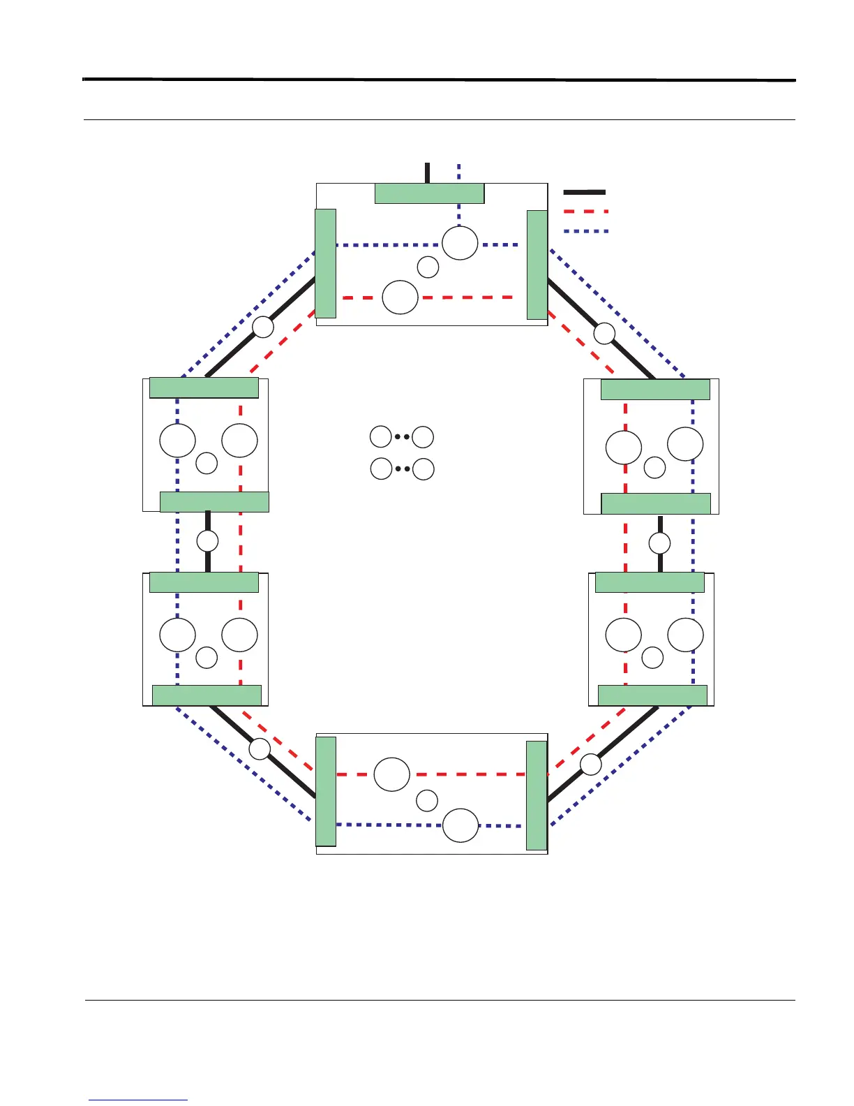
FIGURE 4-12 EPSR Network with Multiple Link Faults
In this network, systems C, D and E are isolated from the core network. Moreover if link 5 between system E
and F is restored, there is no Ring-Up-Flush FDB message, the ports on link 5 cannot be changed to Forwarding,
and systems D and E will still be cut off from traffic, even though link 5 is restored.
= Data VLAN (V_80)
= Physical Link
A
F
= Devices
= Links
V_60
V_80
V_80
V_60
V_80 V_60
B
D
1
5
3
4
1
6
1
6
5
V_80
V_60
D
2.1
A
B
= Control VLAN (V_60)
2.1
0.2
1.1
0.2
1.1
0.1
0.2
1.1
V_80 V_60
B
0.2
1.0
V_80 V_60
B
1.2
0.1
Master
Node
To / From Network
C
E
PP
F
2
SP
X
X
X

 Loading...


