Introduction Configuring SuperLoop
Software Reference for SwitchBlade x3100 Series Switches (Layer Two Switching)
4-136
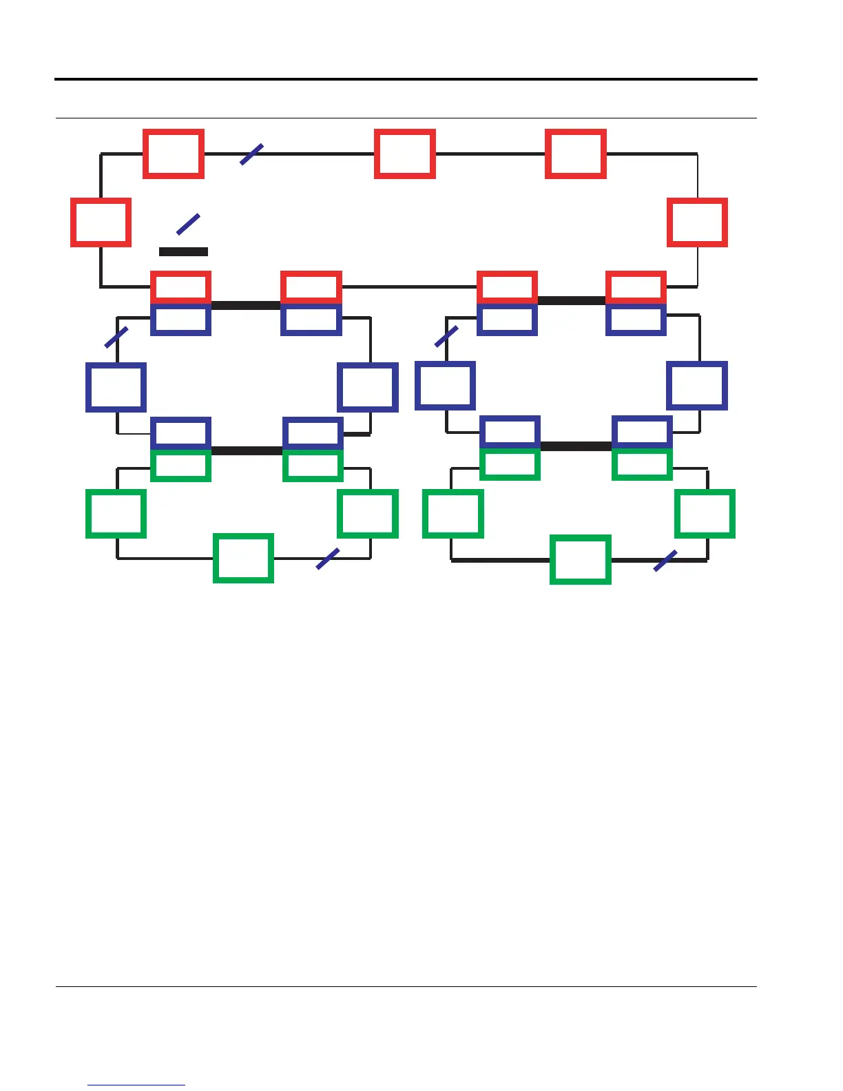
FIGURE 4-15 SuperLoop Example - Disjointed Ring Segments
4.6.12.1 Default Configuration
When an SBx3112 switch is initially booted up, the SuperLoop will be configured as follows:
• No EPSR domains have been created, and so the SuperLoop feature is not configured.
4.6.12.2 Configuration Rules
Since a control VLAN can have many associated data VLANs, and common links can span multiple ring seg-
ments, understanding and then configuring a system with common links with shared data VLANs can become
complex. The following rules should be kept in mind when designing the domains with common links and
shared data VLANs.
1. It is possible that two or more domain instances could share a common link and the same data VLAN(s),
and yet each domain could still have its own unique set of data VLANs. To prevent this configuration, note
the following:
M1
M2
T2
T2
M2
T1
T1
T1
127
126
126
126
126
127
125 125 125 125
127 127
126
Ring Segment Priority 127
Note 1
Note 1
Note 2 Note 2
Note 1
Note 1
Note 1
Note 1
= Common Link
= Blocked SP interface
= All interfaces not
numbered are 0 (default)
Note 2
= With non-shared common link,
can use same priority number
Ring Segment Priority 126
Ring Segment Priority 125 Ring Segment Priority 125
EPSR_Topology_SuperLoop_complex1
Ring Segment Priority 126
126
126 126
125 125
126 126
125 125
127 127
126 126
T1
T1
T2
T2
T3
T3
T3
T3
T3
M3 M3
T2
T3
T2
T3
T2
T3
T1
T2
T1
T2
T1
T2

 Loading...


