Introduction EPSR and (R)STP Interaction
Software Reference for SwitchBlade x3100 Series Switches (Layer Two Switching)
4-146
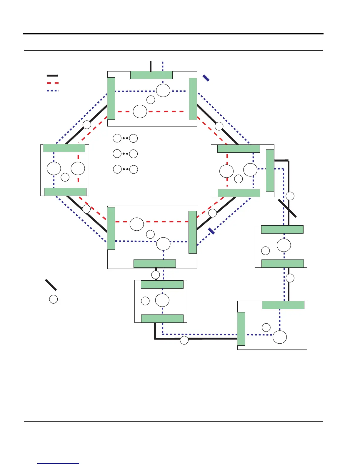
FIGURE 4-17 Possible EPSR/RSTP Configurations
Note: The Multiple Spanning Tree Protocol (MSTP) is also available (refer to Section 4.5). However,
implementing MSTP and EPSR features on the same system is not recommended, and so is
explained separately.
= Data VLAN (V_80)
= Physical Link
A
D
= Devices in EPSR topology
= Links
V_60
V_80
V_80
V_60
V_80 V_60
B
C
1
2
3
4
1
8
V_80
V_60
0.3
A
= Control VLAN (V_60)
= data VLAN is blocked
over Physical Link 3 (SP)
0.1
0.2
0.1
0.2
0.2
0.1
0.2
0.1
PP
SP
Master Node
To / From Network
EPSR_STP_Interop_60
V_80
E
0.1
0.2
V_80
G
0.1
0.2
0.2
0.3
V_80
F
0.2
0.1
= physical link is blocked
by STP over Physical Link 8
5
6
7
8
C
G
= Devices in RSTP topology
3
= path costs set so will
never be blocked by STP
unless no other choice
U
B
D
U
D
D
U
D
U
U
U
= Upstream (by UCP)
D
= Downstream (by UCP)
Root
Bridge

 Loading...


