Configuring UCP with ESPR Introduction
4-181
Software Reference for SwitchBlade x3100 Series Switches (Layer Two Switching)
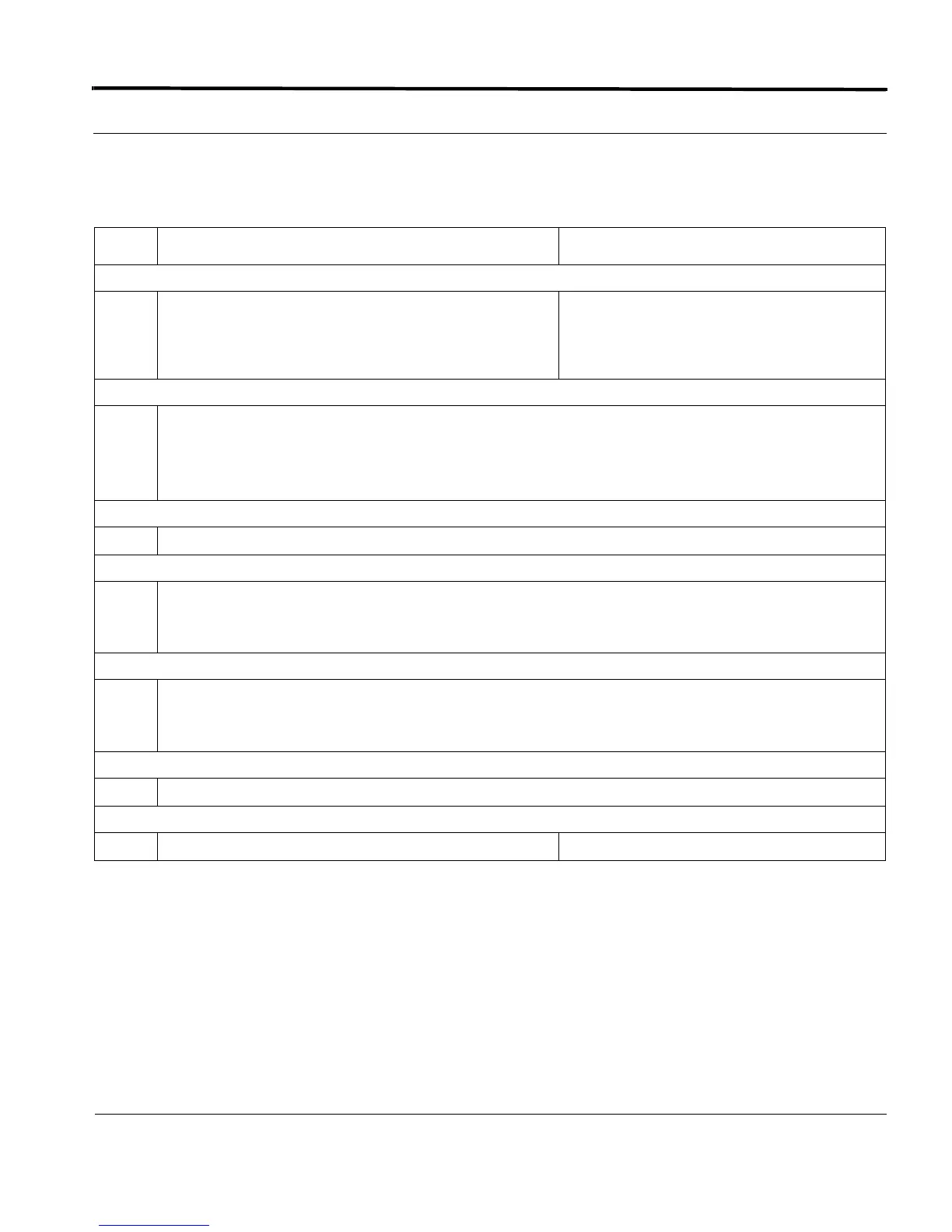
TABLE 4-24 Configuration Procedure for UCP/EPSR/RSTP
Step Command Description/Notes
Create the Control VLAN and add it to the appropriate interfaces
1
CREATE VLAN vid=1200 FORWARDING-
MODE=STANDARD
ADD VLAN 1200 INTERFACE 10.1,11.2
FRAME=TAGGED
The default for FORWARDINGMODE is
STANDARD, but this is shown here to contrast
this with the Data VLAN
Create the Data VLAN as a UFO VLAN and give it the attributes to use UCP and PRIMARYUPSTREAM
2
CREATE VLAN vid=600 FORWARDINGMODE=UPSTREAMONLY
ADD VLAN 600 INTERFACE 10.0,10.1,11.2 FRAME=TAGGED
SET VLAN 600 INTERFACE 10.1,11.2 FORWARDING=UCP
SET VLAN 600 INTERFACE 10.0 FORWARDING=PRIMARYUPSTREAM
Set the GE interfaces as having a direction of NETWORK
3
SET INTERFACE=10.0,10.1,11.2 GE DIRECTION=NETWORK
Configure the node for EPSR.
4
CREATE EPSR=ALLIED TRANSIT
ADD EPSR ALLIED VLAN=1200 TYPE=CONTROL
ADD EPSR ALLIED VLAN=600 TYPE=DATA
Configure the node for RSTP. The path cost for the primary node should be lower than the secondary node.
5
SET STP PROTOCOL=RSTP FORCE
SET STP INSTANCE=MAIN INTERFACE=10.0 PATHCOST=40000
SET STP INSTANCE=MAIN INTERFACE=10.1,11.2 PATHCOST=10
Enable STP
6
ENABLE STP
Using the SET command, you can turn on the Enhanced Recovery feature.
7
SET EPSR allied ENHANCEDRECOVERY=ON

 Loading...


