– To do so, press the function selector button “CAR” on the MMI
operating unit. The main menu “adaptive air suspension” will
appear.
– Use the rotary pushbutton to select the “automatic” level.
Further information on the vehicle level can be found in the ⇒
MMI Operating Manual
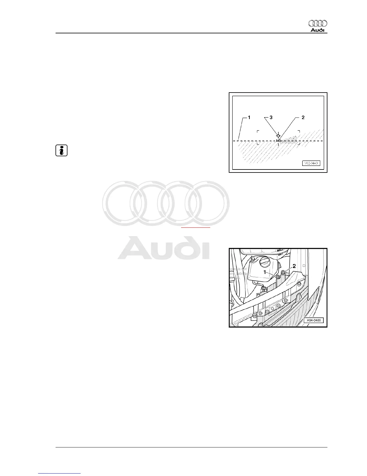
♦ The horizontal light-dark border should coincide with the set‐
ting line -1- of the test surface.
♦ The break-away point -2- between the horizontal section of the
light-dark border on the left and the rising section on the right
should coincide with the vertical line running through the cen‐
tral point -3-. The bright spot in the centre of the beam should
be to the right of the vertical line.
Note
♦
To make it easier to find the break-away point -2-, cover and
uncover the left half of the headlight (as seen in direction of
travel) a few times. Then check the dipped beam again.
♦
If dipped beams have been adjusted correctly the centre point
of the main beam should lie on central point -3-.
♦
If using an old test screen with a 15 ° setting line, the adjust‐
ment procedure is the same as for the new screen. Disregard
the 15° setting line to avoid incorrect settings.
– If headlight setting is not OK, adjust headlights ⇒ page 141 .
3.3.3 Adjusting headlights
Headlight (left-side)
Adjuster screws on left headlight:
1 - Height/lateral adjuster screw
2 - Height adjuster screw
The arrangement on the right headlight is symmetrically opposite.
– Only turn adjuster screw -2- to adjust the height.
– To make a lateral adjustment, turn adjuster screws -1- and
-2- the same number of turns.
3.4 Preparations before working on head‐
lights
Depending on the engine version, access to the headlight bulbs
could be obstructed. In this case, additional steps must be per‐
formed.
3.4.1 Removing power steering reservoir
Special tools and workshop equipment required
Audi A8 2003 ➤
Electrical system - Edition 08.2014
3. Halogen headlights (USA vehicles) 141