Protected by copyright. Copying for private or commercial purposes, in part or in whole, is not
permitted unless authorised by AUDI AG. AUDI AG does not guarantee or accept any liability
with respect to the correctness of information in this document. Copyright by AUDI AG.
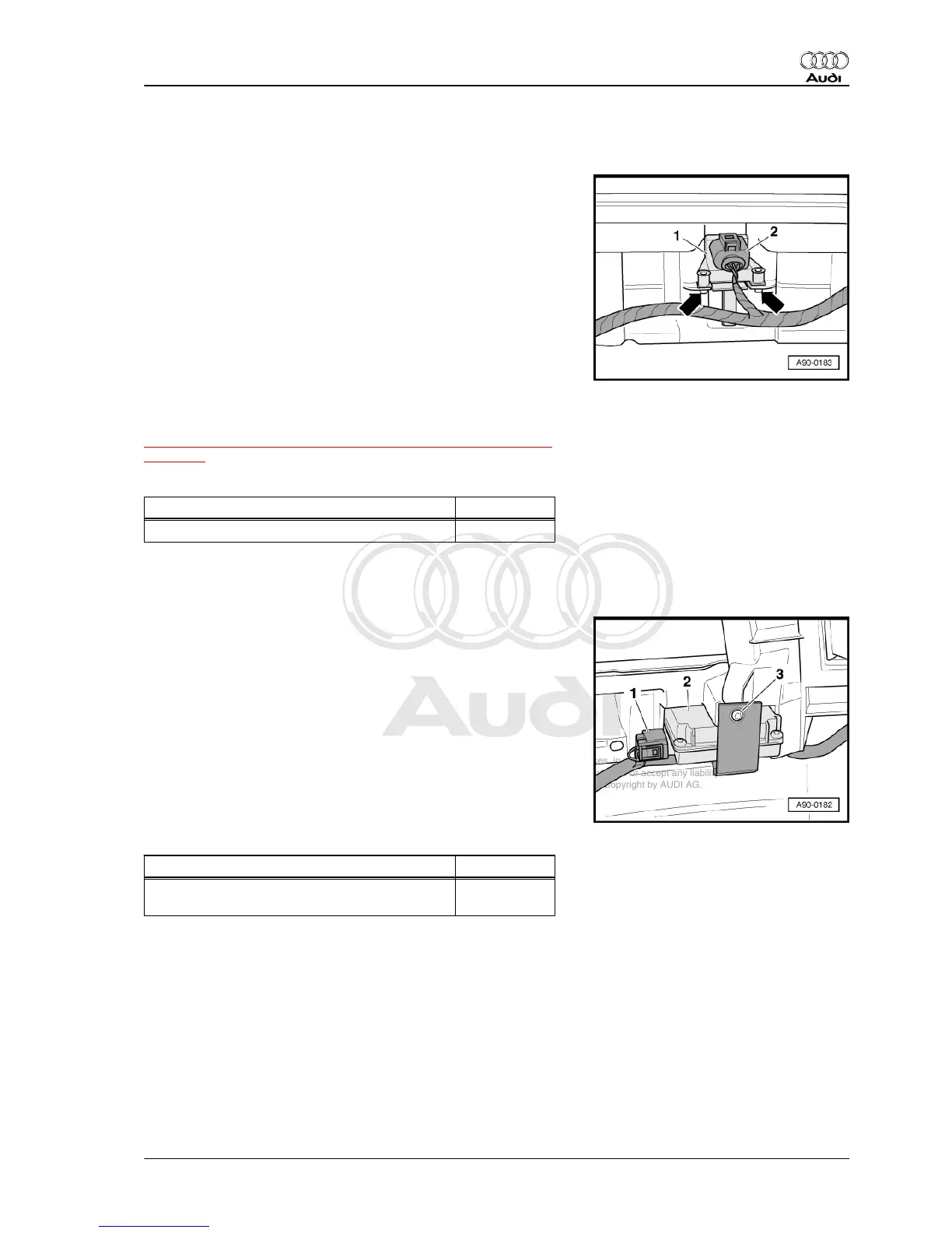
1.5 Removing and installing radio-control‐
led clock receiver - J489-
Removing
– Remove rear bumper cover ⇒ Rep. gr. 63 .
– Unplug electrical connector -2- at radio-controlled clock re‐
ceiver - J489- -item 1-.
– Unscrew bolts -arrows- and detach radio-controlled clock re‐
ceiver - J489- .
Installing
Installation is carried out in the reverse order; note the following:
– Install rear bumper cover ⇒ Rep. gr. 63 .
Vehicles with lane change assist:
Lane change assist control unit -J769- / -J770- must be recali‐
brated whenever bumper cover has been removed
⇒ “12.5 Calibrating lane change assist - test equipment layout”,
page 321 .
Tightening torque
Component Nm
Radio-controlled clock receiver to bumper 2.5
1.6 Removing and installing garage door
operation control unit - J530-
Removing
– Remove front bumper cover ⇒ Rep. gr. 63 .
– Unscrew bolt -3- and detach retainer.
– Take garage door operation control unit -2- out of bumper
cover.
– Unplug electrical connector -1-.
Installing
Installation is carried out in the reverse order; note the following:
– Install front bumper cover ⇒ Rep. gr. 63 .
Tightening torque
Component Nm
Garage door operation control unit to bumper
cover
2.5
Audi A8 2003 ➤
Electrical system - Edition 08.2014
1. Instrument cluster 95