Protected by copyright. Copying for private or commercial purposes, in part or in whole, is not
permitted unless authorised by AUDI AG. AUDI AG does not guarantee or accept any liability
with respect to the correctness of information in this document. Copyright by AUDI AG.
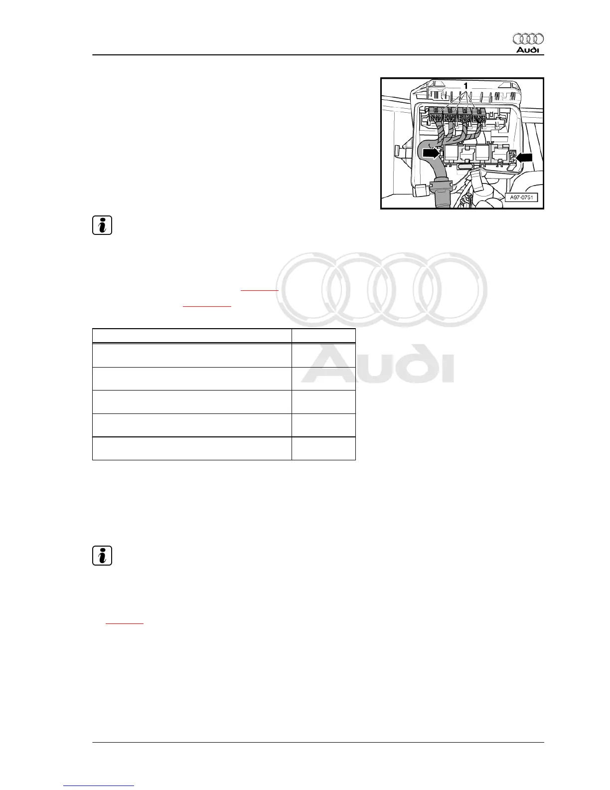
– Unplug electrical multi-pin connectors -1-.
– Release fasteners -arrows- and lift off auxiliary relay carrier in
electronics box.
– Disengage engine wiring harness at electronics box and move
clear.
– Unbolt and lift off electronics box.
– Unclip plug-in sockets for electrical multi-pin connectors.
Installing
Installation is carried out in the reverse order; note the following:
Note
Refit all cable ties at the same locations when reinstalling.
– Install glove box ⇒ Rep. gr. 68 .
– Connect battery. Steps required ⇒ page 3 .
– Adjust wiper arms ⇒ page 114 .
Tightening torques
Component Nm
Electronics box (plenum chamber) to outside of
body
2
Engine control unit to electronics box (plenum
chamber)
2
Electronics box (plenum chamber) to inside of
body
3
Inner cover inside to electronics box (plenum
chamber)
3
Control unit for front display and information
control panel - J523- to body
4
3.2 Removing and installing relay and fuse
holder in electronics box (plenum cham‐
ber)
Removing
Note
All cable ties unfastened or cut open during removal must be re‐
attached in same position when installing.
– With ignition switched off, disconnect earth cable at battery
⇒ page 2 .
Audi A8 2003 ➤
Electrical system - Edition 08.2014
3. Relay carriers, fuse carriers (engine compartment) 335