Protected by copyright. Copying for private or commercial purposes, in part or in whole, is not
permitted unless authorised by AUDI AG. AUDI AG does not guarantee or accept any liability
with respect to the correctness of information in this document. Copyright by AUDI AG.
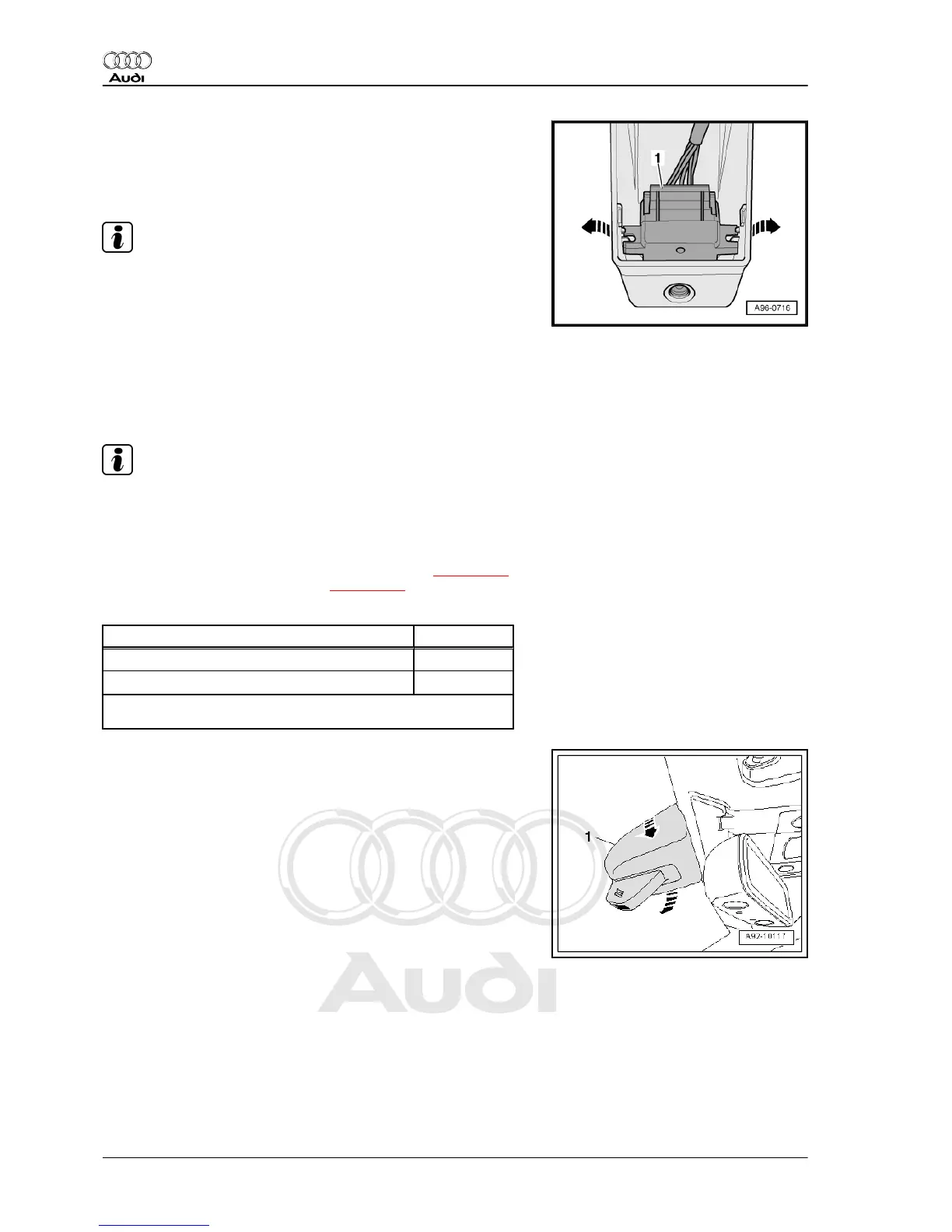
– Press cover apart slightly at both sides -arrows- and take out
humidity sender - G355- -item 1-.
Installing
Installation is carried out in the reverse order; note the following:
Note
♦
After removing centre bracket for sun visor, tapped holes for
centre bracket for sun visor must be cleaned of remaining
locking fluid. Otherwise the new bolts can seize when screw‐
ing in and they can shear off if they have to be removed again
later.
♦
Use a thread tap to clean.
♦
Renew self-locking bolts.
– Carefully insert humidity sender - G355- in side guides.
Note
If humidity sender - G355- is not installed correctly, it will not be
centred in hole in cover.
– Install interior mirror ⇒ Rep. gr. 68 .
– Install front interior light: vehicles up to 08.2007 ⇒ page 292 ,
vehicles from 08.2007 onwards ⇒ page 293 .
Tightening torques
Component Nm
Moulded headliner to body 4
Centre bracket for sun visor to body
4
1)
•
1)
Renew bolts.
8.3 Removing and installing humidity send‐
er - G355- - vehicles with lane departure
warning
– If control unit is to be renewed, select the “Replace control unit”
function for appropriate control unit in ⇒ Vehicle diagnostic
tester.
– Pry open cover -1- (top) at interior mirror base -arrows-.
Audi A8 2003 ➤
Electrical system - Edition 08.2014
304 Rep. gr.96 - Lights, bulbs, switches - interior