Protected by copyright. Copying for private or commercial purposes, in part or in whole, is not
permitted unless authorised by AUDI AG. AUDI AG does not guarantee or accept any liability
with respect to the correctness of information in this document. Copyright by AUDI AG.
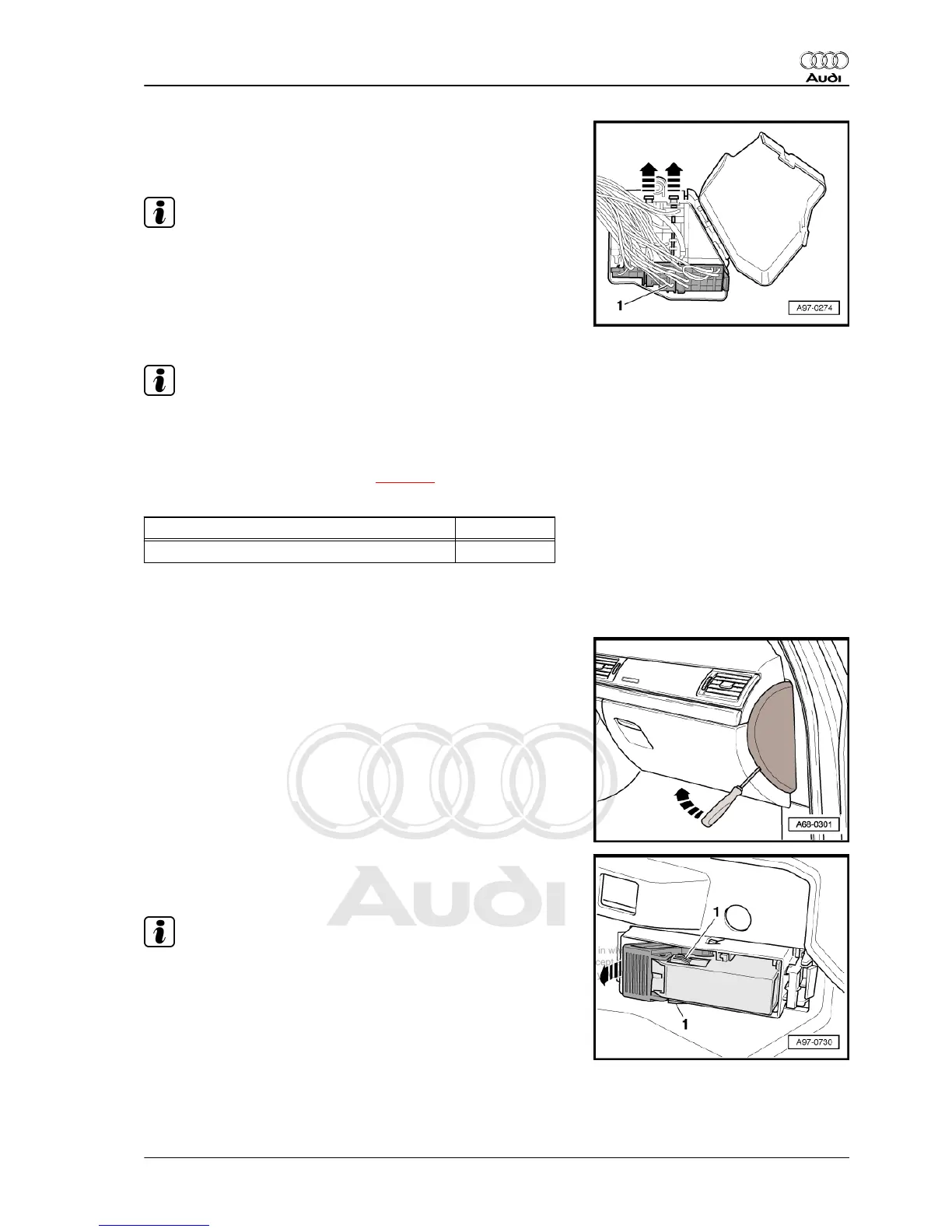
– Detach retaining strip for connectors -arrows- and take con‐
nectors out of fuse holder.
– Unclip socket -1-.
Note
Exact contact assignment of fuse holder in dash panel (right-side)
can be found in applicable current flow diagram ⇒ Current flow
diagrams, Electrical fault finding and Fitting locations.
Installing
Installation is carried out in the reverse order; note the following:
Note
Refit all cable ties at the same locations when reinstalling.
– Install glove box ⇒ Rep. gr. 68 .
– Connect battery. Steps required ⇒ page 3 .
Tightening torque
Component Nm
Fuse holder to central tube for dash panel 3
4.8 Removing and installing CAN separat‐
ing connector (right-side) -T46b-
Removing
– Switch off ignition and take out ignition key.
– Use screwdriver to pry off dash panel end trim (right-side)
-arrow-.
– Press retaining tabs -1- at multi-pin connector.
– Release retaining clip -arrow- and unplug connector.
Note
Exact contact assignment of CAN separating connector (right-
side) can be found in appropriate current flow diagram ⇒ Current
flow diagrams, Electrical fault finding and Fitting locations.
Installing
Install in reverse order.
Audi A8 2003 ➤
Electrical system - Edition 08.2014
4. Relay carriers, fuse carriers (vehicle interior) 343