Protected by copyright. Copying for private or commercial purposes, in part or in whole, is not
permitted unless authorised by AUDI AG. AUDI AG does not guarantee or accept any liability
with respect to the correctness of information in this document. Copyright by AUDI AG.
– Unplug electrical connector (top) at return ring with slip ring.
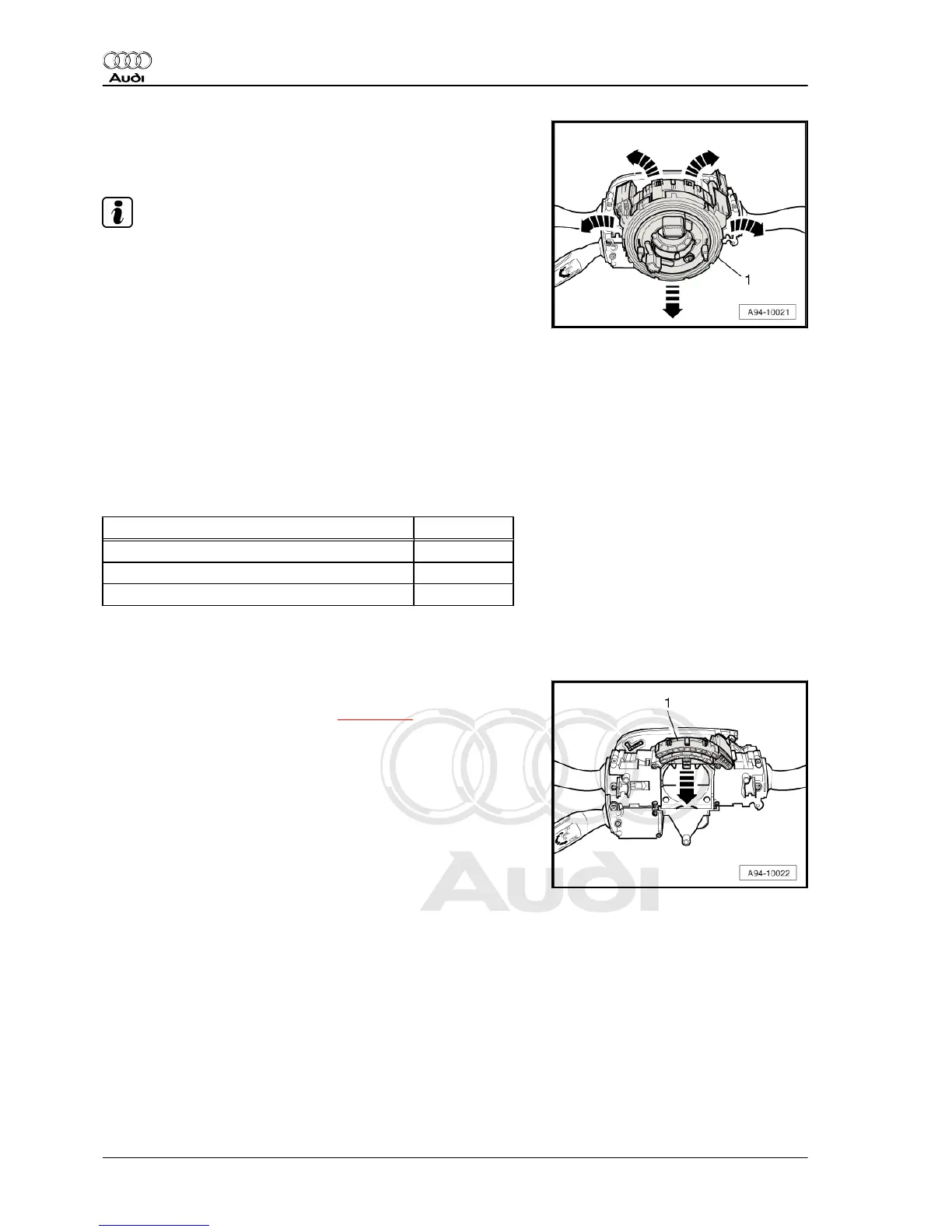
– Carefully release retaining hooks -arrows- and pull return ring
with slip ring -1- off steering column switch module.
Note
Steering column switch module has been removed in illustration
for greater clarity.
Installing
Installation is carried out in the reverse order; note the following:
– Make sure all retaining hooks and the electrical connectors are
properly engaged.
– Insert top trim for steering column switch in hooks for bottom
trim, press both sections together and tighten bolts.
– Install driver's storage compartment ⇒ Rep. gr. 68 .
– Install steering wheel ⇒ Rep. gr. 48 .
– Install airbag unit ⇒ Rep. gr. 69 .
Tightening torques
Component Nm
Steering column switch module 3
Trim for steering column switch 1
Trim (bottom) to steering column 2.5
22.4 Removing and installing steering angle
sender - G85-
Removing
– Remove return ring with slip ring ⇒ page 244 .
– Pull off steering angle sender - G85- -item 1- -arrow-.
Installing
Install in reverse order.
– Perform calibration of steering angle sender -G85- in “Guided
Functions” after renewing steering angle sender ⇒ Vehicle di‐
agnostic tester.
22.5 Removing and installing steering col‐
umn electronics control unit - J527-
Removing
– If control unit is to be renewed, select the “Replace control unit”
function for appropriate control unit in ⇒ Vehicle diagnostic
tester.
– Continue to follow the instructions on the display of the vehicle
diagnostic tester.
Audi A8 2003 ➤
Electrical system - Edition 08.2014
246 Rep. gr.94 - Lights, bulbs, switches - exterior