892-0000010B OM
127
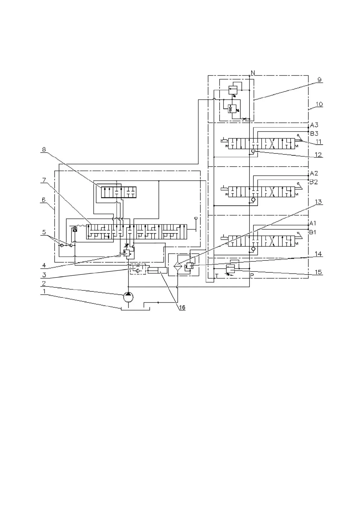
The HLL circuit hydraulic diagram with the RP70-1221.1S distributor installed is
shown in Figure 3.11.4.
1 - tank; 2 - pump; 3 - retarding valve; 4 - priority valve; 5 - check valve; 6 - draft
(positional) control unit; 7 - sleeve; 8 - spool; 9 - bypass valve; 10 - RP70-1221.1S
distributor; 11 - spool; 12 - check valve; 13 - hydraulic system filter; 14 - filter valve; 15
- safety valve; 16 - cylinder.
Figure 3.11.4 – HLL circuit hydraulic diagram with the RP70-1221.1S distributor in-
stalled.