892-0000010B OM
77
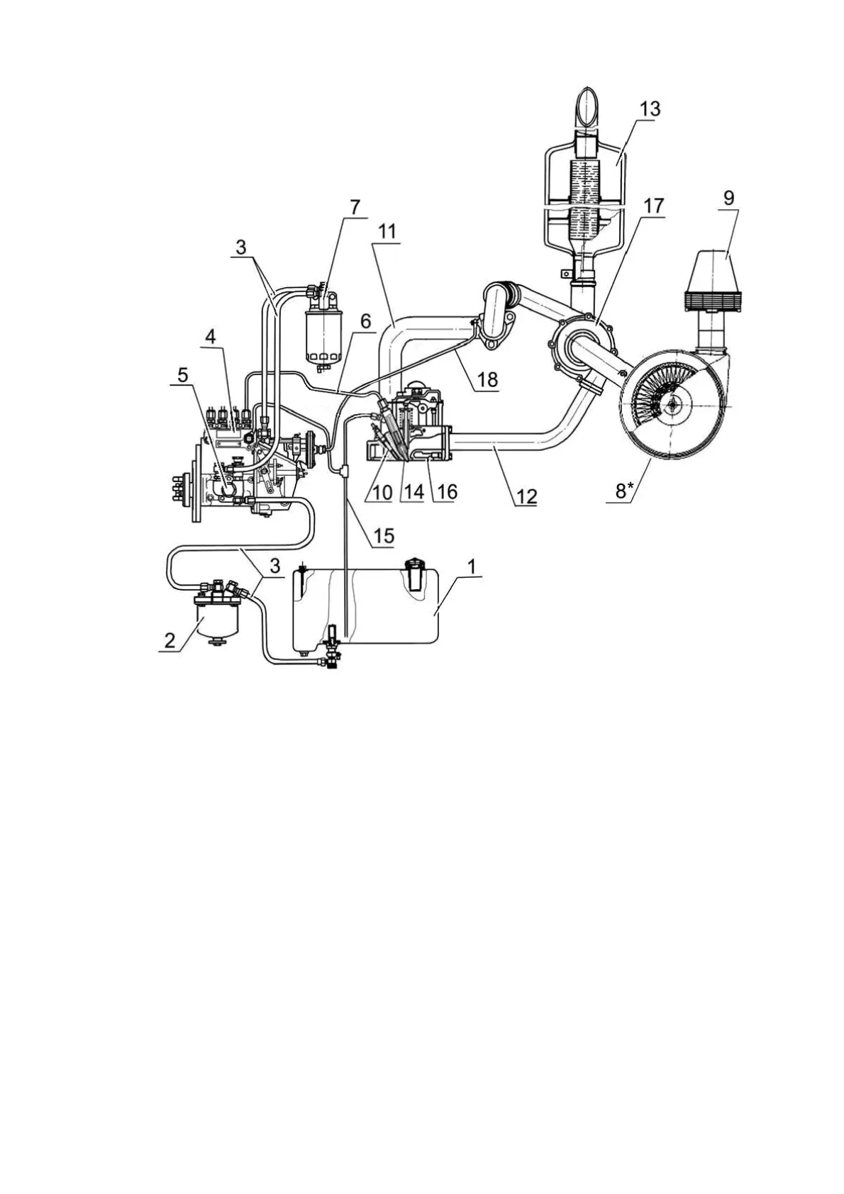
1 - fuel tank; 2 - coarse fuel filter; 3 - low pressure fuel pipes; 4 - high pressure fuel pump; 5
- fuel priming pump; 6 - high pressure fuel line; 7 – fuel fine filter; 8 - air cleaner; 9 - mono-
cyclone; 10 - glow plug; 11 - intake manifold; 12 - exhaust manifold; 13 - muffler; 14 - injector;
15 - fuel outlet pipe to the tank; 16 - cylinder head; 17 - turbocharger; 18 - pneumatic cor-
rector tube.
Figure 3.1.2 – Diagram of fuel supply system of D-245.5 engine.
Injector 14 (Figure 3.1.2) is designed to inject fuel into the engine cylinder. It provides
the necessary fuel atomization and limits the start and end of the feed.
Coarse filter 2 is used for preliminary fuel purification from mechanical impurities and
water. The coarse filter consists of a body, a reflector with a grid, a diffuser, a cup with a
dampener. Sludge is drained from the filter through a hole in the bottom of the cup, closed
with a stopper.
Fine filter 7 serves for the final purification of fuel. The fine filter has a replaceable
paper element. Fuel, passing through the curtains of the paper filter element, is cleaned of
mechanical impurities. In the lower part of the filter housing there is a hole with a plug for
draining the sludge. To remove air from the fuel supply system, a special plug is located on
the filter cover.
Air cleaner 8 is used to clean the air sucked into the cylinders. Detailed information
about the structure and operation of the intake duct of the BELARUS-892/892.2 tractors is
presented in subsection 3.1.2 "Engine air cleaning system".
Engine cooling is liquid with forced circulation of coolant from a centrifugal pump.
The temperature of the coolant in the system is controlled by the temperature gauge on the
instrument panel. The temperature gauge sensor is installed in the cylinder head. A place is
provided for installing the sensor in the thermostat housing. Do not operate the engine when