892-0000010B OM
87
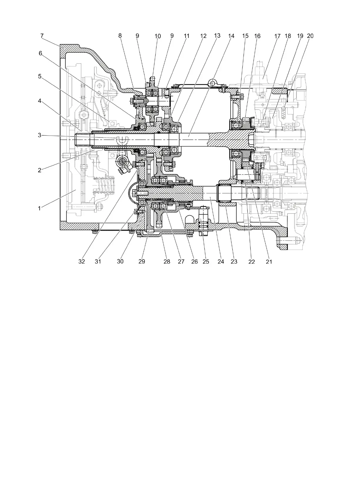
1 - flywheel; 2 - floating bushing; 3 - yoke; 4 - hub; 5 - release bearing; 6 – shifter bracket; 7
- clutch housing; 8, 9, 12, 13, 15, 27, 31 - bearing; 10 – hydraulic pump drive gear; 11 - axle;
14 - power shaft; 16 - driving gear of the reverse gear unit; 17 - reverse gear unit control
mechanism; 18 - synchronizer; 19 - driven gear of the reverse gear unit; 20 - ball; 21 - idle
gear of the reverse gear unit; 22 - needle bearing; 23, 30 - needle bearing with outer race;
24 - driven shaft of the PTO drive; 25 - control shaft; 26 – toothed clutch; 28 - driven gear of
the PTO drive (1000 rpm mode); 29 - driven gear of the PTO drive (540 rpm mode); 32 -
drive pinion-shaft of the PTO drive.
Figure 3.2.6 – Clutch housing with reverse gear unit
3. Reducing synchronized gear unit (Figure 3.2.7), which is designed to obtain an
additional series of speeds necessary for operation with agricultural machines. The gear unit
is located between the clutch housing and the gearbox. The primary shaft of the gearbox
has synchronizer 18 installed. The synchronizer train, controlled by control mechanism 17,
can engage with driven gear of the reducing gear unit 19 (lower pass of the reducing gear
unit) or with drive gear of the gear unit 16 (higher pass of the reducing gear unit). The lever
for switching the reducing synchronized gear unit is installed in the tractor cab.