9
Operation
120/198 CCD CAM 100 – Installation and Operating Manual
9.6.2 Display of CAN Bus Information
9.6.2.1 Display of the CAN Bus Status
The virtual LED indicates the current status of the CAN bus con-
nection.
Colour
LED
Status CAN Bus
Designation
Meaning
red
ON BUS OFF
There is a bus problem
present.
The interface controller is
in Bus-Off mode.
FLASHING SYNC ERROR
The device is not receiving
any sync frames.
green
ON OPERATIONAL
The device is in operational
mode.
FLASHING PREOPERATIONAL
The device is in pre-
operational mode.
Initialization is completed.
The device can be started.
9.6.2.2 Display of the CAN Bus Address
The two digits indicate the set CAN bus address of the CCD camera.
To set the CAN bus address, see Setting the CAN Bus Address,
page 153.
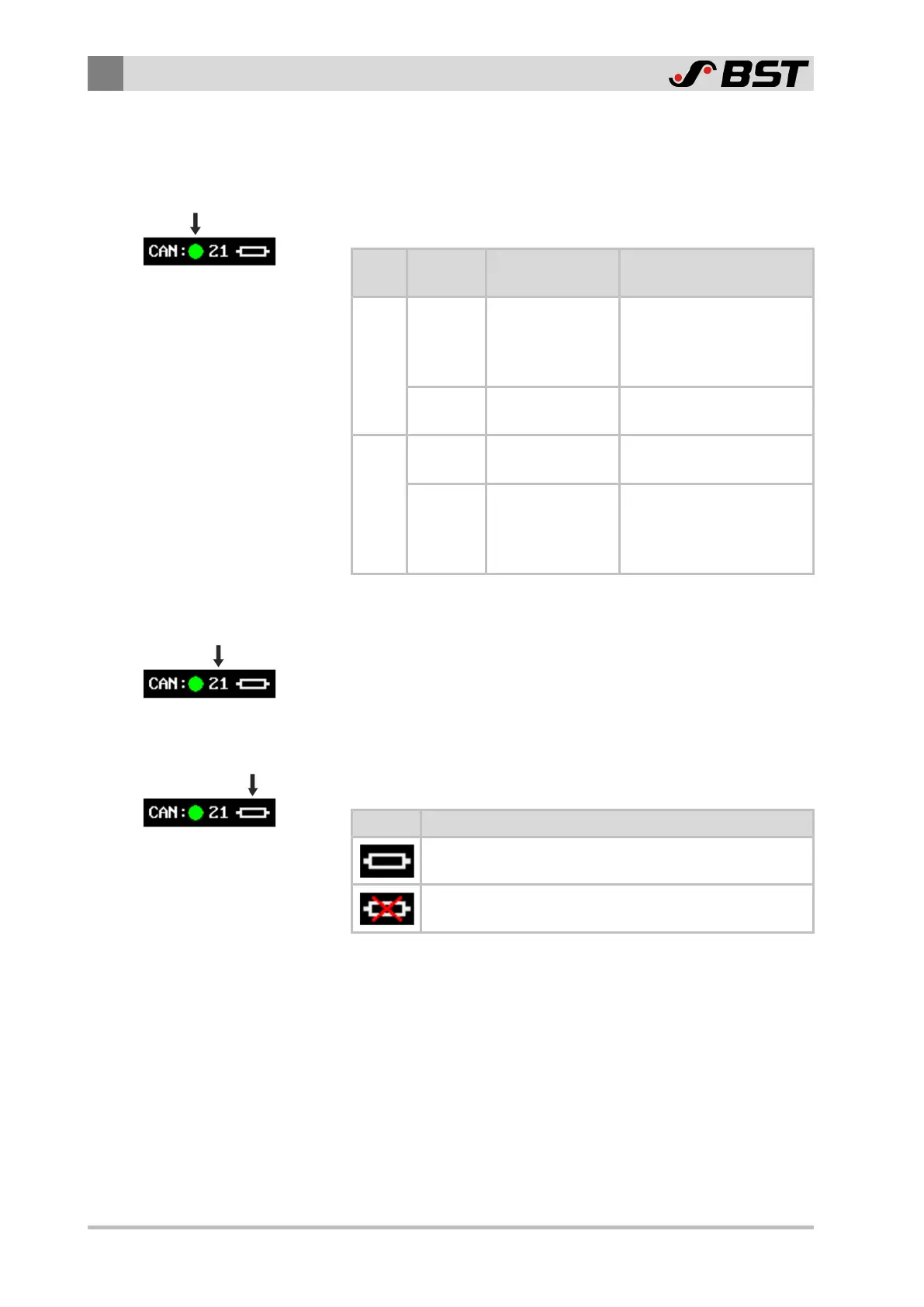
9.6.2.3 Display of the CAN Bus Terminating Resistor Status
The symbol shows the state of the internal CAN bus terminating
resistor of the CCD camera.
Symbol Meaning
CAN bus terminating resistor is activated
CAN bus terminating resistor is deactivated
To activate the CAN bus terminating resistor, see Activating the
CAN Bus Terminating Resistor, page 155.
 Loading...
