3
Design and Function
30/198 CCD CAM 100 – Installation and Operating Manual
3.7.2 Service LEDs
There are six service LEDs located behind the cover of the service
opening. They show the different operating and error states of the
CCD camera.
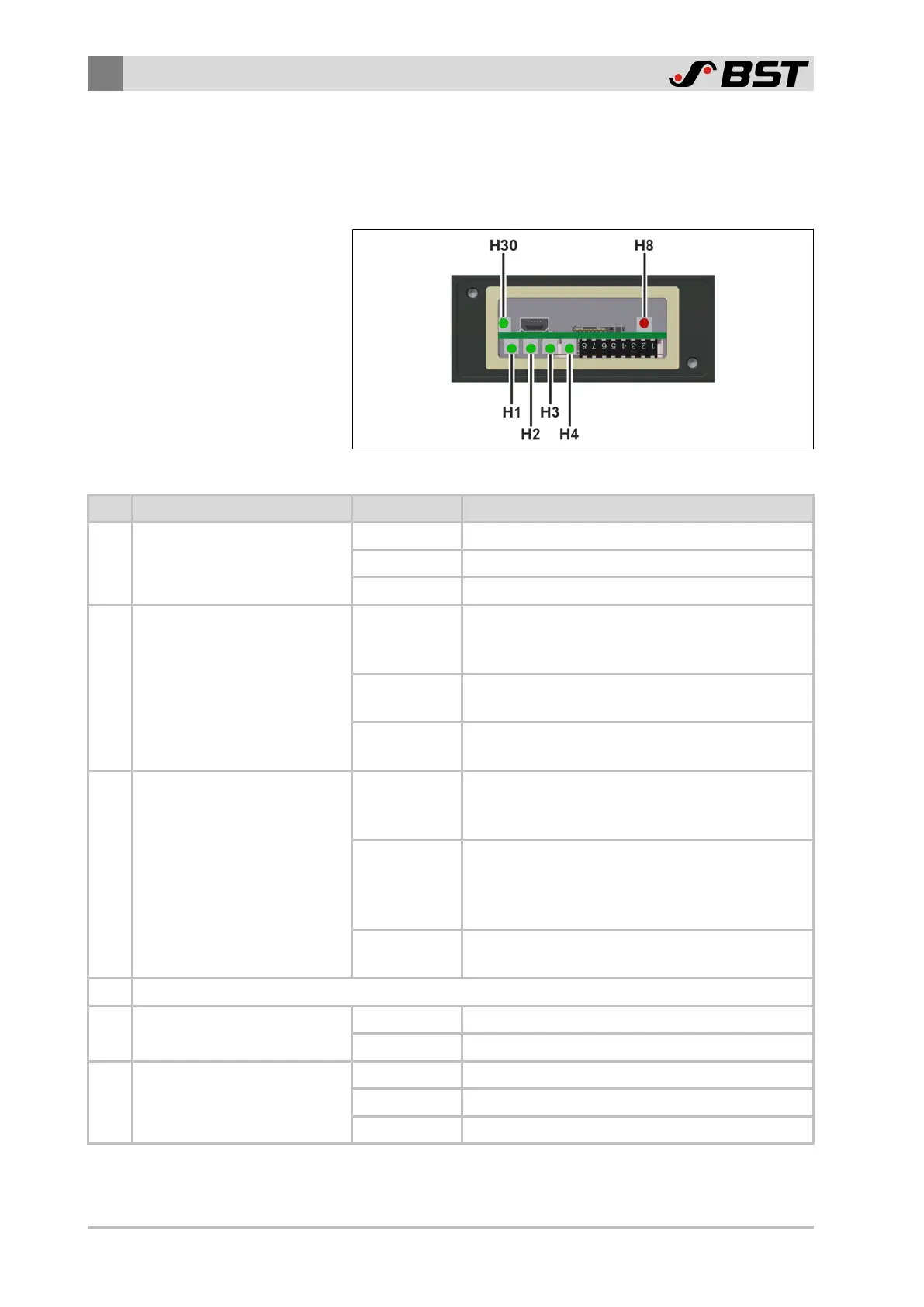
Fig.12: Service LEDs
LED Function Status Meaning
H1 Display of device status
OFF The unit is in an undefined state.
FLASHING The unit program is running correctly.
ON The unit is in an undefined state.
H2 Display of bus status
OFF
NO ERROR
The unit is running ‘OK’.
No errors present.
3x FLASHING
SYNC ERROR
No SYNC message is received.
ON
BUS OFF
The interface controller is in Bus-Off mode.
H3
Display of CAN bus operating
mode
OFF
STOPPED
The unit is in the initialization phase.
No data transfer takes place.
FLASHING
PREOPERATIONAL
The unit is in PREOPERATIONAL mode.
Initialization is completed.
The unit can be started.
ON
OPERATIONAL
The unit is in OPERATIONAL mode.
H4 reserved
H8 Display of power supply status
OFF Operating voltage 24V⎓ not available
ON Operating voltage 24V⎓ available
H30
Display of network connection
status
OFF Ethernet connection not available
FLASHING Data transfer is taking place.
ON Ethernet connection available
 Loading...
