7
Electrical Connection
60/198 CCD CAM 100 – Installation and Operating Manual
7.3 Connections
7.3.1 Overview
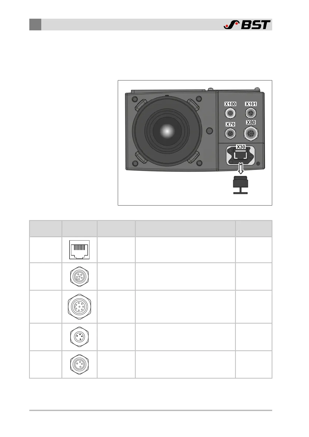
The following connections are located at the bottom of the housing.
Remove
dust protection cap
Fig.34: Connections
Designation Socket/
Plug
Interface Utilization Remark
X30 Ethernet
Connection of an external control system
(e.g. PLC, PC, machine control system)
Remove dust
protection cap
X70
Current
outputs
Connection external illumination
X80
Digital
inputs/outputs
Connection synchronization component
(e.g. encoder)
X100
CAN bus
(plug)
Connection BST controller
X101
CAN bus
(socket)
Connection of further BST CAN bus
participants (e.g. second CCD camera)
Internal 1:1
connection
with X100
 Loading...
